0

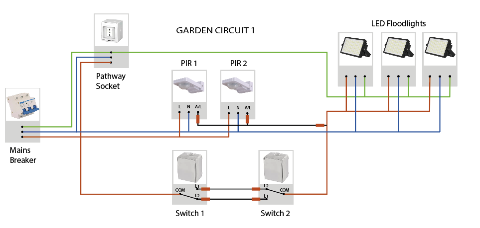
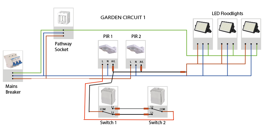
I have a pathway through the garden to get to my gate which i want ot illuminate with 3 floodlights. Its not certain that PIR sensors alone will work so I want to be able to override them by switching on the lights EITHER at the gate OR at the front door, but otherwise have the PIR sensors work as usual. I have watched every youtube video and tutorial and I think this is correct however I'm not sure about whether there is a dangerous loopback in this circuit. Can I loopback the earth like this and can I wire multiple PIRs and switches together all in parallel like this (European colouring below)
Circuit diagram

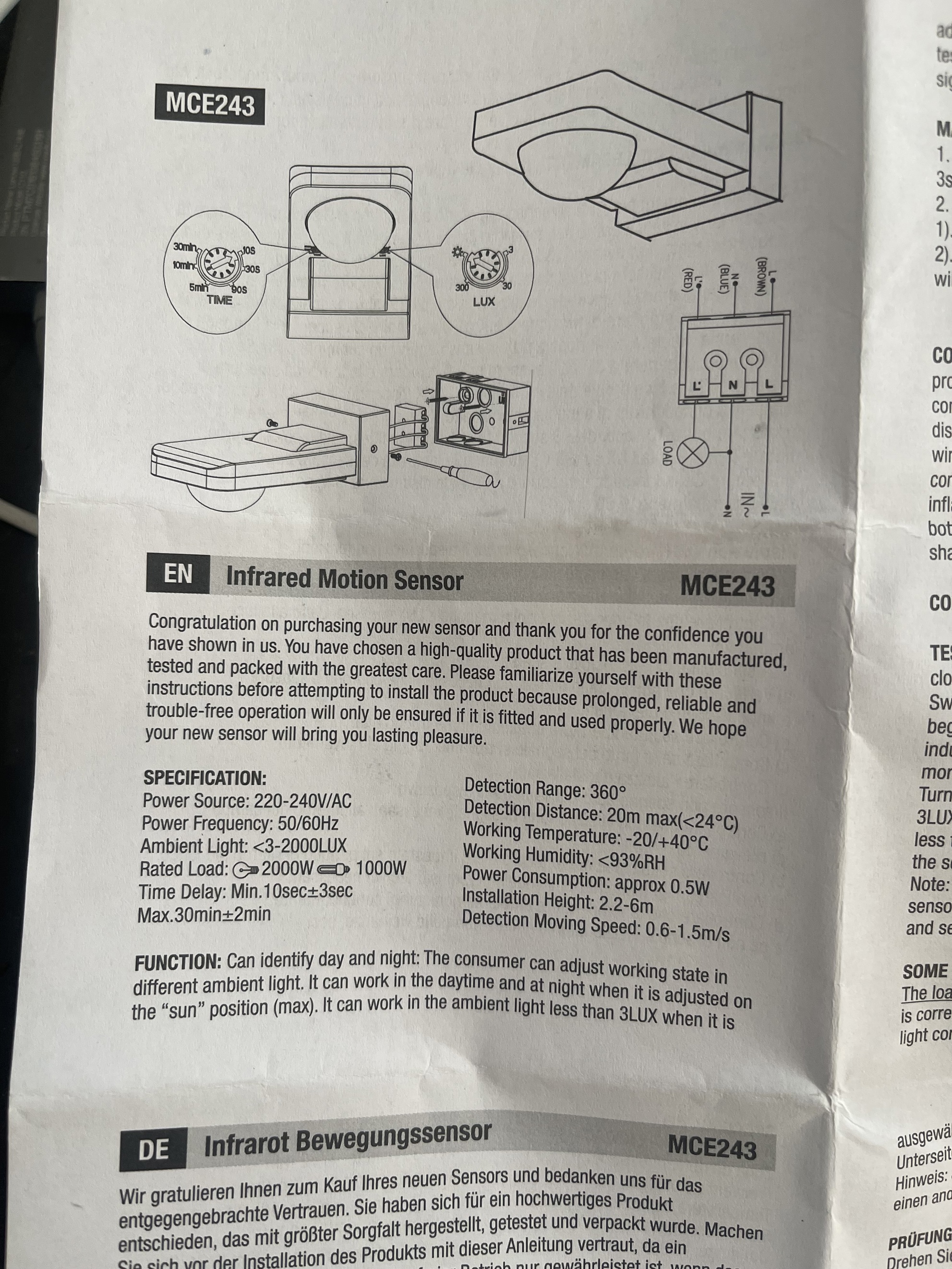
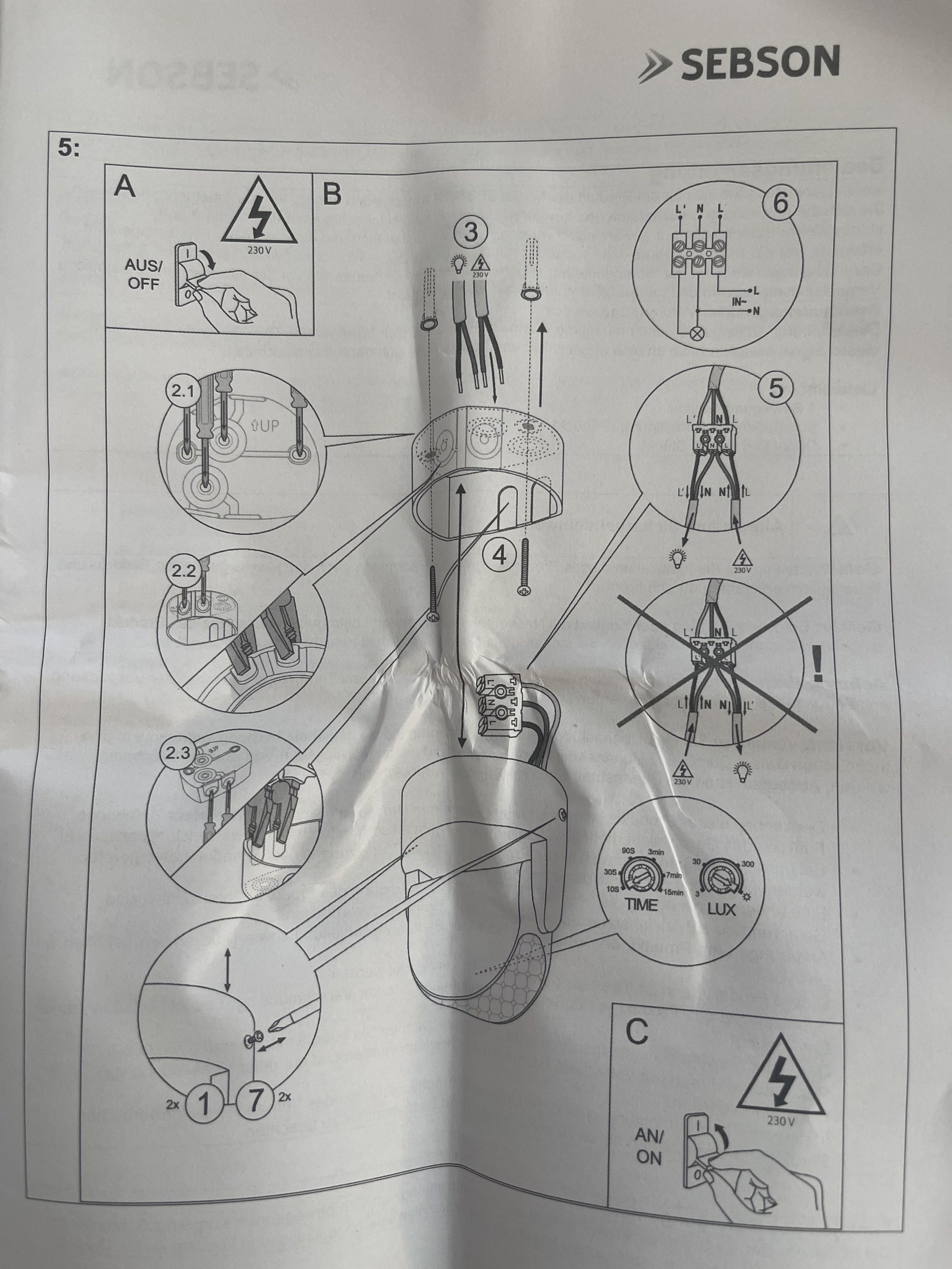
enter image description here EDIT: added the specsheet install details from sensors below

enter image description here

enter image description here

2

3 Answers 3

4

Yeah, that looks fine. You have to watch your cable routing to make sure you don't have imbalance current in any cable. I.e. currents must be equal/opposite in any given cable and a clamp ammeter around any cable must read 0 due to mutual cancel-out.

If I was making a wiring diagram it would look like this. Omitted for clarity: protective earth/ground.

enter image description here

5
  • Well then the wiring as drawn has a problem because the current through the switches will be returning on a neutral on a different cable
    – DJ.
    Commented Nov 7 at 23:12
  • @DJ I assumed you drew a schematic, which doesn't think about wire routing. Here let me edit my answer with what I would do. Commented Nov 8 at 3:20
  • Oh like a switch loop, yes that would work better than my relay!
    – DJ.
    Commented Nov 8 at 5:22
  • I don't think most European codes are concerned about unequal currents provided they're not significant (tens of amps) or passing through steelwork. Using 4C+E cable could also be an alternative though you have to use an alternate way of wiring the two-way. Commented Nov 8 at 11:59
  • 16 amps max in the garden circut. not passing through steelwork only along pvc trunking along garden walls and the underground (soil) for a small part
    – Alex
    Commented Nov 10 at 10:52
1

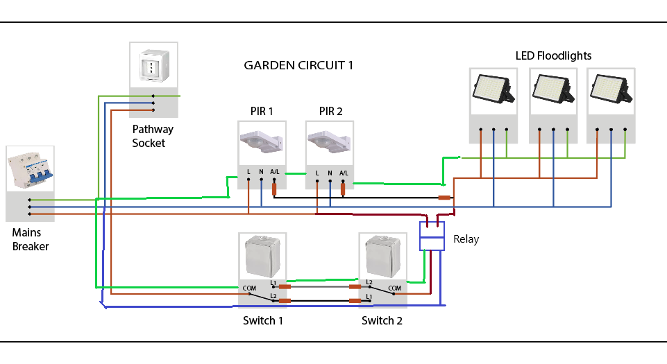
I am assuming the PIR sensors are line voltage and not low voltage. The problem with your proposed wiring circuit is that the hot and neutral for a circuit must travel in the same cable. However your power coming from the switches is returning on a neutral on a different cable which is against code.

The only way I can think of to fix this is to add a relay switch which would isolate the two circuits and ensure balanced power in all cables. Also the grounds should also be in the same cables so I updated your diagram to add the relay switch and the proper placement of neutrals and grounds

enter image description here

1

In the USA you can't run a separate parallel path for live but not neutral. Presumably in other countries too.

More importantly you've designed a terrible user interface. With three way switches and two parallel PIRs a user cannot know whether and why the switches are on or off.

I suggest you do this differently. If you describe your actual needs in a new question, from the perspective of a user who did not design and install it, we can suggest appropriate switches to achieve it.

3
  • I want the lights to go on as i enter/exit the garden along the path to the gate. the path goes from the house, about 30 meters to the gate. The PIRs are not failsafe (there are trees and bushes) but I want them anyway for intruders etc so i want a switch at either end.
    – Alex
    Commented Nov 10 at 13:36
  • Make that the question.
    – jay613
    Commented Nov 10 at 13:53
  • OK thanks for the suggestion. Apologies for all the confusion. here is the new question: diy.stackexchange.com/questions/309791/…
    – Alex
    Commented Nov 10 at 14:23

Your Answer

By clicking “Post Your Answer”, you agree to our terms of service and acknowledge you have read our privacy policy.

Not the answer you're looking for? Browse other questions tagged or ask your own question.