0

I'm trying to upgrade some light switches to smart switches that require neutral wires. I did a couple single pole switches months ago which, with some trial and error, worked fine. I'm stuck on at least one 3-way.

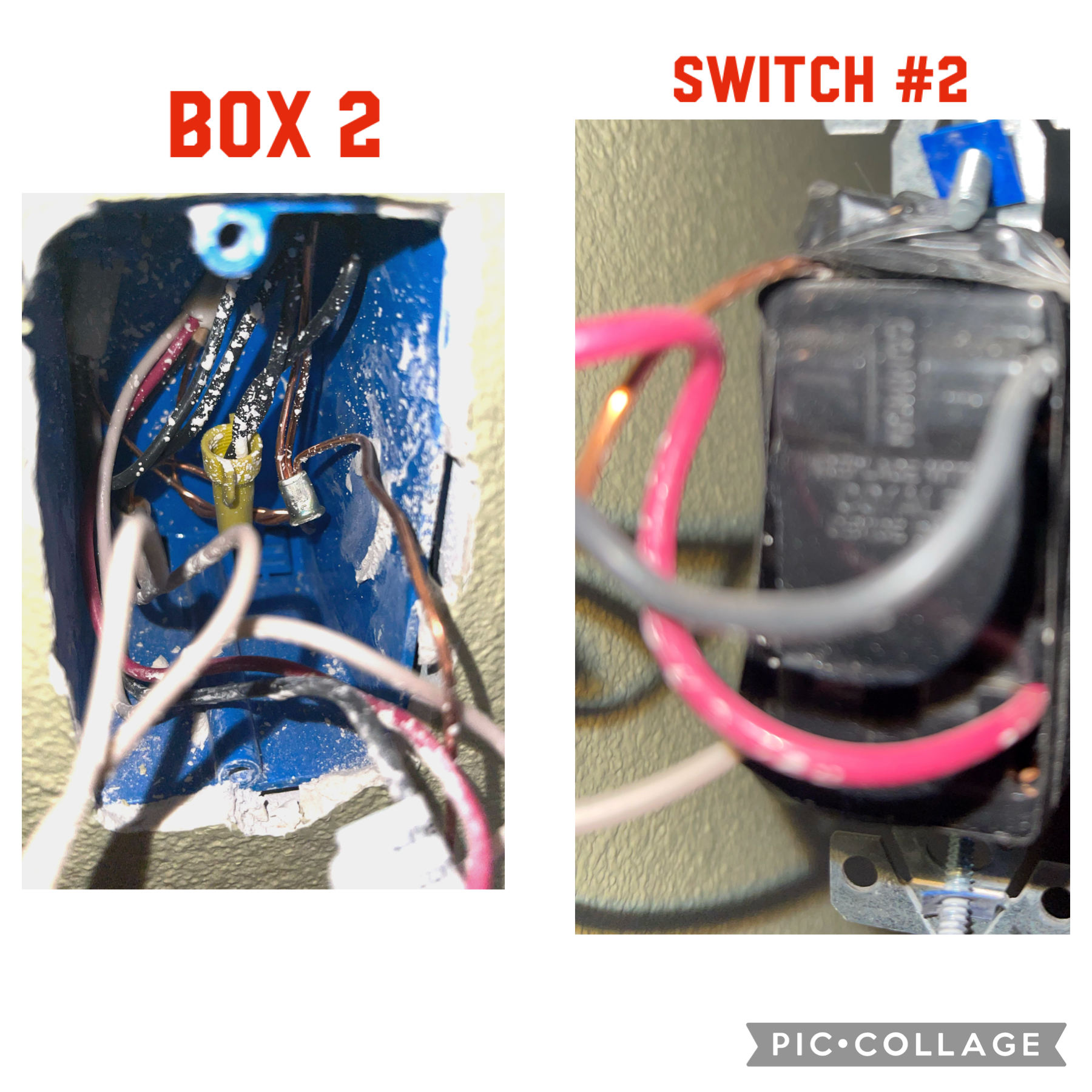
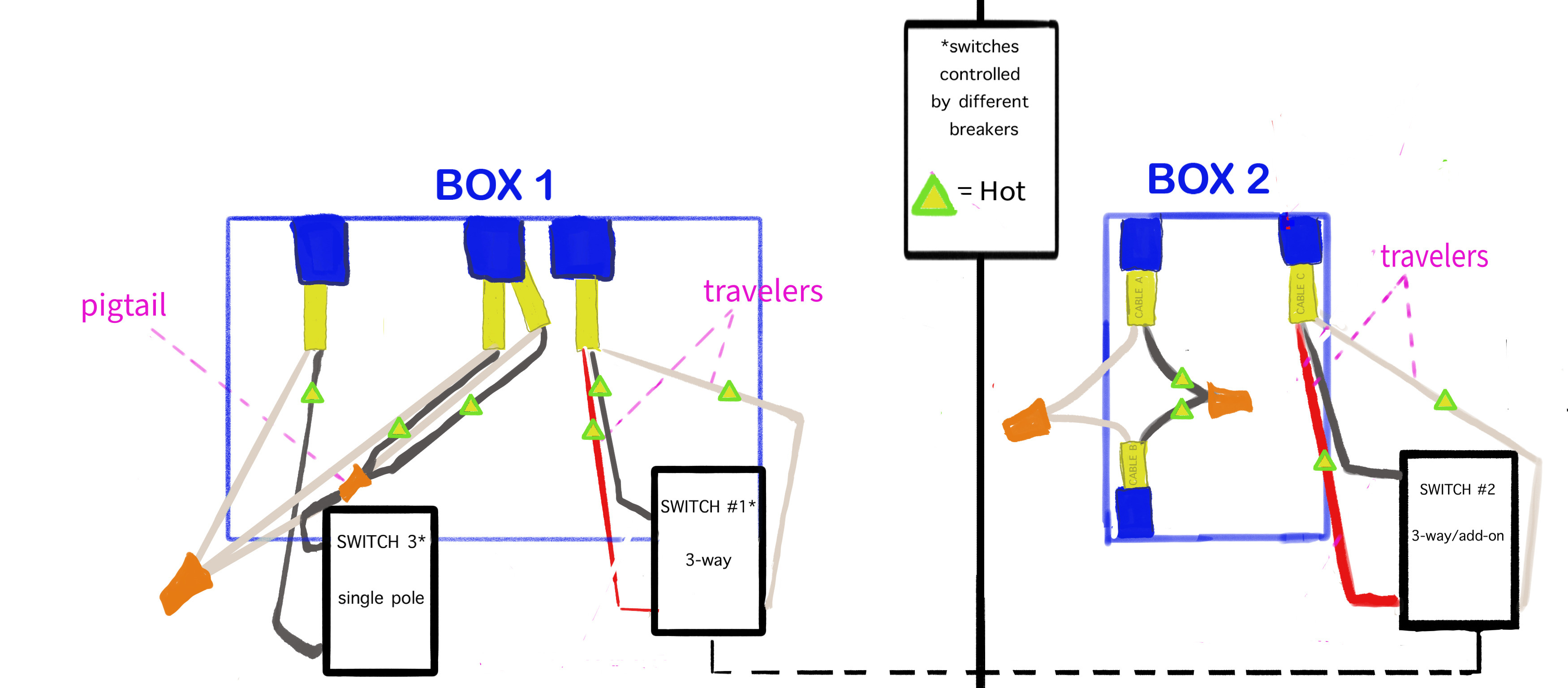
The house was remodeled in 2005, so there are neutral wires. However, the 3-way switch I'm currently trying to change is housed in one double-gang box (Box 1, Switch #1) and one single box (Box 2, Switch #2). In the double-gang box, the other switch (Switch #3) is controlled by a different breaker.

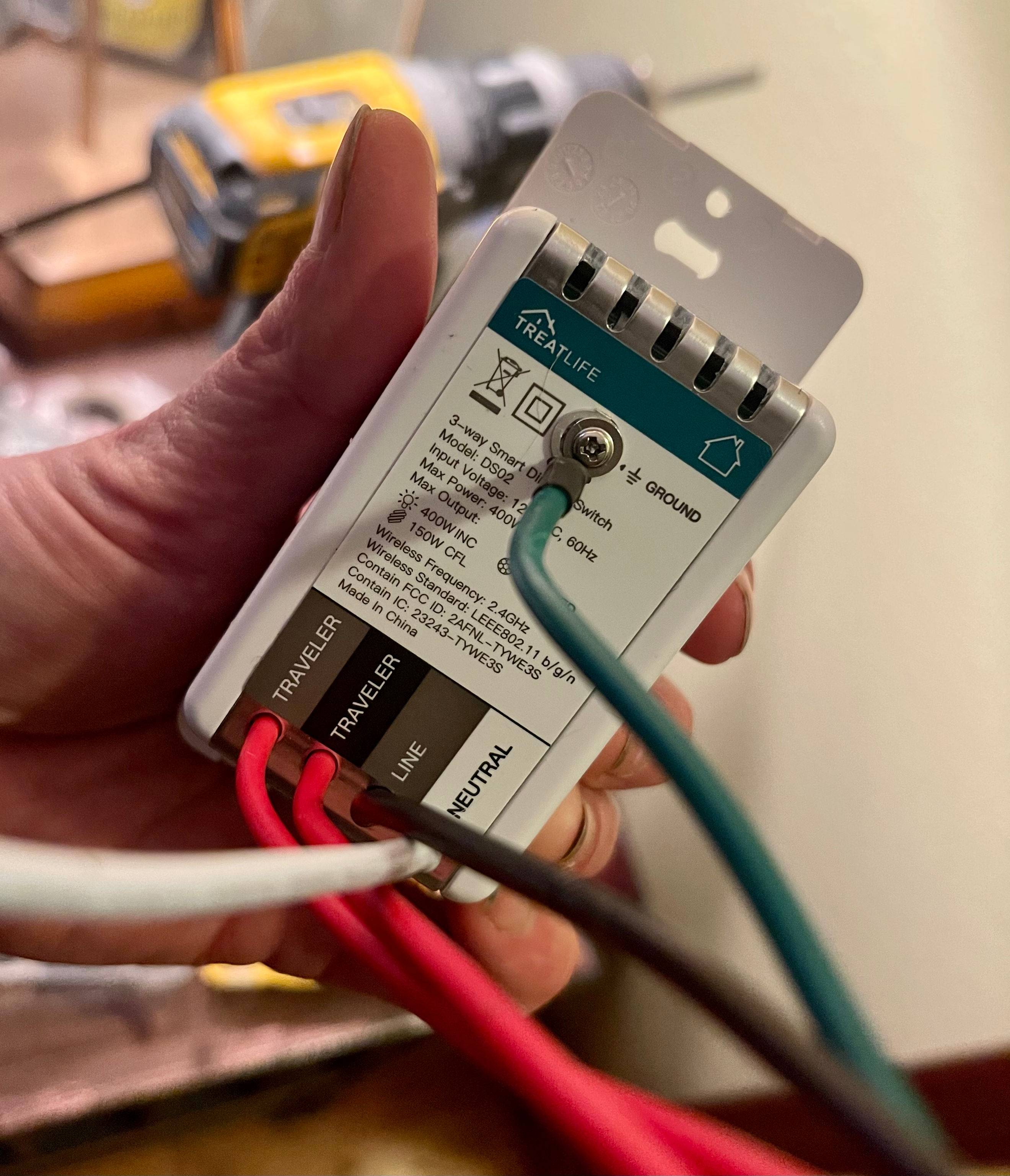
The 3-way switches in both boxes 1 and 2 use a white wire as a traveler, which leaves me without a white neutral wire for the smart switch.

Initially, I thought Switch #1 was the input because it's the main (most accessible, most used) switch. However, after realizing that Switch #3, right next to it, is on a different circuit (signifying the start and end of a circuit?), I suspect that Switch #2 is the input. Please correct me if I'm wrong and/or if there's a way to verify that.

So far, I've tried:

  • Box 1: pigtail power from Cables 2&3 (Box 1) to the line/load on the smart switch (using red & black as travelers, white as neutral)
  • Box 1: pigtail from the neutral bundle (Cables 1,2,3) to the neutral on the smart switch (maintaining the white and red as travelers)
  • Box 2: Pigtail power from the black bundle (Cables A&B) to the line/load of the smart switch.

Please let me know if you need more information or if my pics/illustration need clarification.


An extra credit question is: how do I know which neutral wire to use when changing out switch #3 (Box 1), given that wires from Cables 1,2, and 3 are all employed for that single switch?

Products I'm using are Treatlife 3-way smart dimmer switch and TP-Link Kasa Smart Wifi Light Switch Dimmer (as titled on boxes)

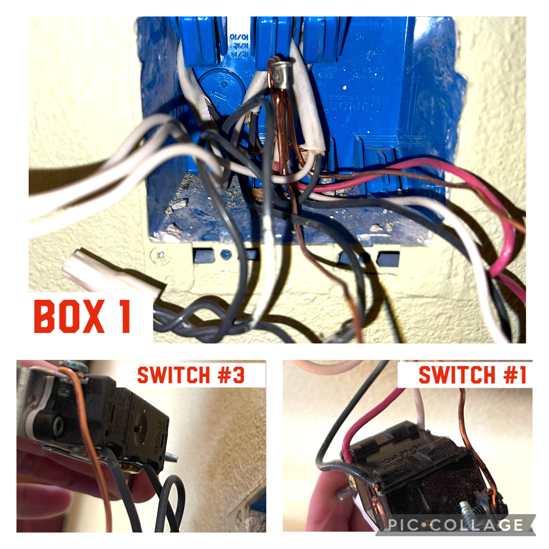
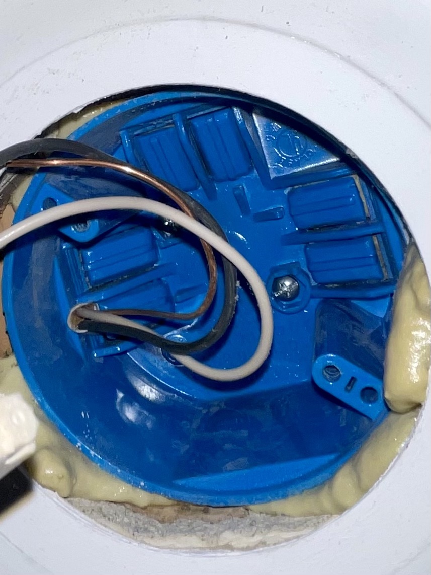
Box1 Box2 3wayswitch IllustrationUPD Light Fixture Box

8
  • 2
    Trial and error is BAD. There are lots of combinations that will work and then kill you. An example would be tying a smart switch neutral to ground for lack of a neutral. That said, exchanging among the hot wires going to a switch is generally no-risk, but as soon as neutral and ground enter the picture, lookout. Commented Jan 17, 2022 at 0:55
  • 1
    Anyway, "no wire connections other than ground" is not surprising in box 1; the other 3 cables are connected in normal ways and it sounds like this 3-way is a spur, unrelated. However in box 2, it's a bit more surprising. Were there really no connections of the two /2 cables and the 3-way switch? Have you seen the wiring arrangement at the light? Wired as it is in your drawing, does it currently work? Commented Jan 17, 2022 at 1:02
  • @Harper-ReinstateMonica The connections in the boxes were exactly as shown, and the light (from both switches) works as depicted in the drawing. I don't know if it makes a difference, but there is another double gang (2 switches) on the other side of the wall of Box 2, on the same circuit. I added a picture of the light fixture wiring. It appears pretty straightforward. Thanks for your input!
    – Jasbro
    Commented Jan 17, 2022 at 2:32
  • @Jasbro -- are you somehow wedded at the hip to the Treatlife dimmer? Commented Jan 17, 2022 at 3:07
  • 1
    @freeman - I didn’t realize that. Thanks for pointing it out.
    – Jasbro
    Commented Jan 17, 2022 at 16:09

1 Answer 1

2

To answer your question, there's a simple rule about where you are allowed to take a neutral: You may use a neutral only if it is in the same cable as a hot wire already going to your switch.

In both your boxes, you have 3-way switches that are totally isolated (except for safety ground) from the other wires in the box. Those must remain isolated, there must be a "Great Wall" between the sections. Even if they're in the same circuit, they're not in the same cable, and that's the rule. NEC 300.3.


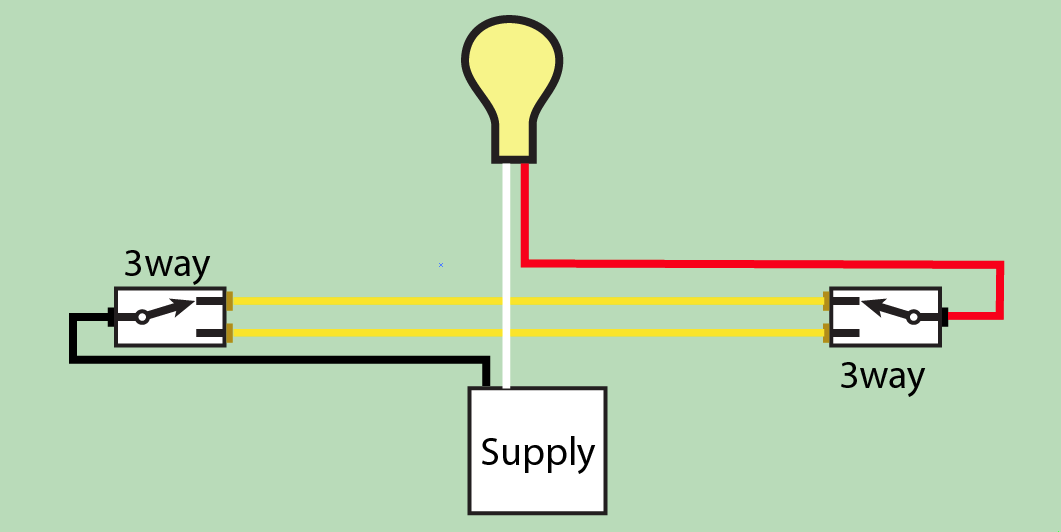
OK, so based on the wiring in the 3 boxes, here's what your wiring looks like.

Yellow = travelers, red = switched-hot, black = always-hot.

enter image description here

Its such a unique case that I had to make a new diagram.

There is some "central hub" point in the diagram middle where 4 cables connect to supply, light and both switches. I couldn't imagine where that hub is, but Code requires that all junction box covers remain accessible without use of tools and without having to disassemble or damage any part of the building finish. Obviously a screwdriver is required to access the cover itself.

That's why I asked so much about the wiring in box 2. Normally having "/2 from power" and "/2 to lamp" would be commonly found in one of the 3-way boxes. But if you're sure of the configuration there, then that's that.

To make smart switches work here, you'll need to find that central junction box. You'll need to reassign ALL wires so that black is always-hot, white is neutral and red is a switched-hot to the lamp. (except the branch to the lamp, where black is "switched-hot".

You don't have any spare wires for inter-switch communication, so that will need to happen wirelessly or with power line signaling. Your smart switch "master" can go in either box, but the other switch will have to be a smart-switch "remote" that is compatible with the master.

Lastly, any switch you install in building wiring must be UL-listed (or certain alternative NRTL's such as CSA or ETL). That crosses off any of the cheap Chinese switches sold exclusively by mail-order. These are typically sold on eBay and Amazon by third-party sellers, even though they ship with Prime, and often seem quite snazzy. They use mail-order because it bypasses the consumer safety mechanisms which assure safe product is sold in retail stores.

1
  • Thanks so much for your in-depth response. It’s very helpful and tells me that I need an electrician to help me…after I get a new 3-way switch. Thank you!
    – Jasbro
    Commented Jan 17, 2022 at 16:22

Your Answer

By clicking “Post Your Answer”, you agree to our terms of service and acknowledge you have read our privacy policy.

Not the answer you're looking for? Browse other questions tagged or ask your own question.