0

Some background: I wanted to replace a light fixture but I wanted it to be lower than the previous one so I had to move the wires but when I cut away the wall I saw there was a lot more going on than the wire for the previous light fixture. There are 4 sets of wires going into this box from the back plus another grey one (lower right in picture) that is now disconnected since the wire nuts came apart when I started moving it.

Here's a picture image
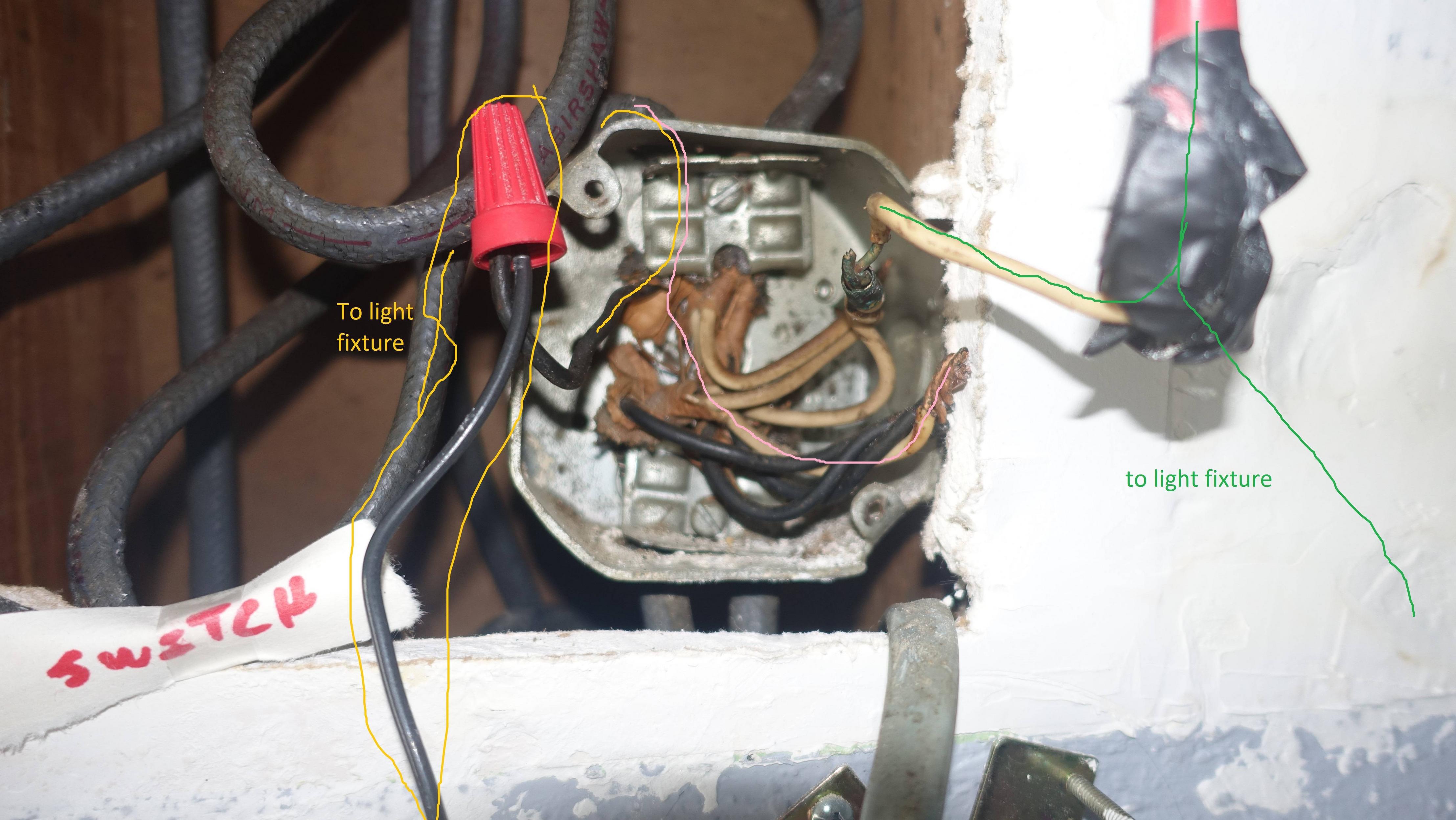
I tried to draw a color line to help differentiate the wires.

The wire coming in from the upper left is from the light switch. As you can see the black wire is by itself and just goes to the light fixture. However the white wire goes to where all the other black wires are spliced together. The white wire from the light fixture itself goes to where all the other white wires are spliced together. I opened my light switch plate and the switch has a white wire and black wire connected to it (sorry I forgot to take a picture behind the switch before I put it back together).

The house is at least 50 years old so it isn't too surprising that the wiring is a bit weird.

Why is it this way and not the way this guy does it https://www.youtube.com/watch?v=LSyzLNUoGus

Also, what's the best way to put this back together so it's safe?

**For what it's worth, there was tape wrapped around the splice on the left side of the green line but no cap.

2
  • Looks like you have a switch loop, there using the white as hot to the switch and the black is the return from the switch to the light's black.
    – Dan D.
    Commented Jan 12, 2015 at 18:29
  • @DanD. Just looked up some diagrams of switch loop and I believe you're right. Thanks. Commented Jan 12, 2015 at 18:54

2 Answers 2

1

It's tapped like that because that's the way it was supposed to be done when that work was done. Back in those days (<2011) if you had a single 2-wire feed (romex) to and fro a switch box. The white wire would, according to more recent codes prior to NEC 2011, and possibly then too but not followed, have been taped a solid color other than green to notify you that it is indeed hot.

This is done to ensure the wire feeding power to the light is black as it would/should be in normal situations; it's safety and economy. The other way to deal with this is to pull a 3-wire feed to the switch. Today this is required not to rid the world of the marking style, as it is still permitted under certain exceptions today, but to cover certain types of switches which require it. As recent as NEC 2008 it was not mandatory unless the manufacturer of the device required it.

You should tape it up (the white wire), then replace all those taped joints with wire nuts appropriately sized for the taps.

5
  • 1
    That "useless white that no one wants" is now code required. We are now required to have a neutral at a switch box, even a switch loop. This was a code change in the 2011 NEC. Commented Jan 12, 2015 at 19:42
  • @SpeedyPetey, well I was answering in context of the mind set of the allowance at the time. As far as the code, I'm a commercial electrician so..., it's not actually strictly mandatory. See 2011 NEC 404.2(C) Exception. But excellent point! Commented Jan 12, 2015 at 19:54
  • @SpeedyPetey, edited for time. Commented Jan 12, 2015 at 20:00
  • 3
    No problem. I just wanted to make the point since lots of folks will see this now and in the future. Commented Jan 12, 2015 at 20:23
  • I ended up ripping all that old stuff out, got a new box, used these instead of wire nuts since I don't trust myself to hook up that many wires with wire nuts. Commented Jan 13, 2015 at 5:17
1

The video is wired differently, because the power (feed) goes to the switch first in that situation. In your situation, the power (feed) is at the light.

In your box, the feed comes in and the white grounded (neutral) conductor is connected to the grounded (neutral) conductor of the light, and presumably a feed to another branch of the circuit. The black ungrounded (hot) conductor is connected to a feed to the switch (white wire), and again presumably a feed to another branch. The other conductor from the switch (black wire), is attached to the ungrounded (hot) conductor of the light.

If you follow the circuit, power comes in to the box and goes to the switch. When the switch is closed, power comes back to the light. Once through the light, the circuit is completed back to the "neutral" wire.

To make this installation safe. Use twist-on wire connectors to make; and insulate, all connections.

Your Answer

By clicking “Post Your Answer”, you agree to our terms of service and acknowledge you have read our privacy policy.

Not the answer you're looking for? Browse other questions tagged or ask your own question.