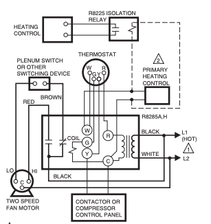
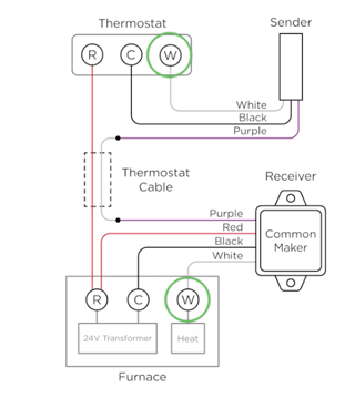
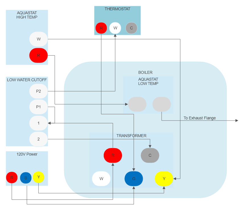
Based on your diagram and the diagram for the R8285D5001, I think the white and red wires on your thermostat are switched from what you would normally expect. Here are some additional diagrams:

Boiler control

Common Maker
So, the "boiler control" is basically a 24v transformer and a relay in one package. The relay is controlled by the G terminal and the W and Y screws are just a convenient way of connecting wires (they are not connected to anything). R and C are the 24v output of the transformer. When R is connected to G, the relay turns on. I'm not sure what the box is that you have labeled "120v power", but it can't be providing 120v to the terminals you show it connecting to. I'm ignoring that in my answer.
The low water cutoff is just a simple switch so you can see how the red comes in, and then white goes out to the thermostat. Then, the R from the thermostat goes to the G terminal on the boiler control. This is the opposite of what the smart thermostat wants, but luckily switching them shouldn't matter to the boiler.
So, your wiring plan looks mostly correct except white and red need to be swapped. Using CM for Common Maker wires. Imagine the P2 terminal as an extension of the R terminal on the transformer.
- CM Red to P2 on low water cutoff with the red thermostat wire
- CM Black to C on the boiler control
- CM White to G on the boiler control
- CM Purple to white wire going to thermostat
With those connections and changes, the thermostat should hook up as described by the rest of the CM documentation. Red to R, purple to
 SDJS_Widget("FE75161A404EAAD9DDBF344E30C02D6059E",67821,1,"");

