2

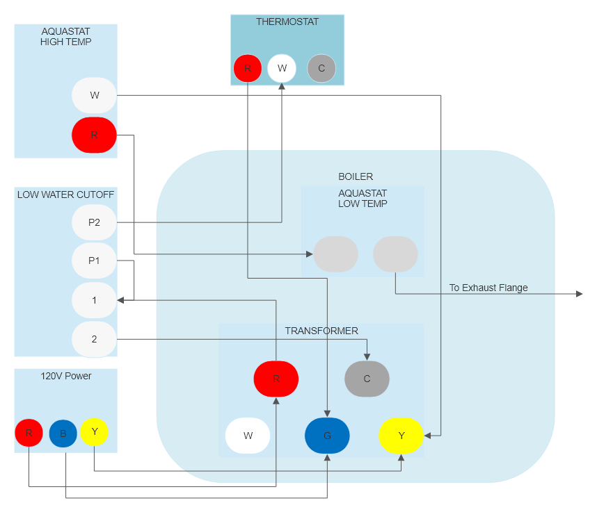
I'm trying to wire up my ecobee in a new house that only has 2 thermostat wires (R, W). I bought a Fast Stat, but I'm unsure how to set it up as I have a complicated setup. There are two aquastats (High and Low Temp), and a low water cutoff. Here is a basic diagram of what wires go where.

SDJS_Widget("FE75161A404EAAD9DDBF344E30C02D6059E",67821,1,"");

I'm unsure which wires I should tap each of the Fast Stat wires into (Red/White/Purple/Black). My guess would be

  • Red to G on Transformer
  • Black to C on Transformer
  • White to P2 on Low Water Cutoff
  • Remove thermostat white from P2 and attach to Fast Stat Purple

Is this correct?

2
  • You need to know if the heating system expects to get 24v voltage from the thermostat or if it just expects a contact closure. HVAC smart thermostats are designed to be used on 24vac systems, and aren't directly compatible with some boilers/oil furnaces without knowing how to wire in your own power and relay. Is there 24v between R and W at the thermostat?
    – JPhi1618
    Commented Nov 2, 2021 at 14:17
  • @JPhi1618 I assume you mean with a multi meter? I'm seeing 26v between the two wires at the thermostat. My transformer in the boiler is a Honeywell R8285D5001 Boiler Control Center that has a relay, not sure if that helps. Thanks
    – nos9
    Commented Nov 2, 2021 at 18:47

1 Answer 1

2

Based on your diagram and the diagram for the R8285D5001, I think the white and red wires on your thermostat are switched from what you would normally expect. Here are some additional diagrams:
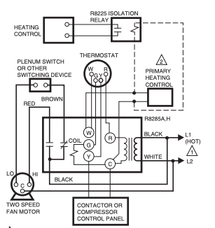
Boiler control
Boiler control

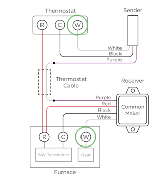
Common maker

Common Maker

So, the "boiler control" is basically a 24v transformer and a relay in one package. The relay is controlled by the G terminal and the W and Y screws are just a convenient way of connecting wires (they are not connected to anything). R and C are the 24v output of the transformer. When R is connected to G, the relay turns on. I'm not sure what the box is that you have labeled "120v power", but it can't be providing 120v to the terminals you show it connecting to. I'm ignoring that in my answer.

The low water cutoff is just a simple switch so you can see how the red comes in, and then white goes out to the thermostat. Then, the R from the thermostat goes to the G terminal on the boiler control. This is the opposite of what the smart thermostat wants, but luckily switching them shouldn't matter to the boiler.

So, your wiring plan looks mostly correct except white and red need to be swapped. Using CM for Common Maker wires. Imagine the P2 terminal as an extension of the R terminal on the transformer.

  • CM Red to P2 on low water cutoff with the red thermostat wire
  • CM Black to C on the boiler control
  • CM White to G on the boiler control
  • CM Purple to white wire going to thermostat

With those connections and changes, the thermostat should hook up as described by the rest of the CM documentation. Red to R, purple to
2
  • Thanks, I'll give this a try later tonight. Regarding the 120v wires. There are thicker gage wires that say 120v on them that are attached to transformer terminals as shown in my diagram. Looking at it again these might go to water pump. There are two conduits that come into the boiler behind the transformer, one from the pump and one from the junction box with the power switch for the boiler.
    – nos9
    Commented Nov 2, 2021 at 20:58
  • 1
    Yea, the transformer/relay is designed to control a 120v fan or pump, so that could be whats going on. The same control unit is used in a variety of applications, so it's pretty generic in what it can control.
    – JPhi1618
    Commented Nov 2, 2021 at 21:02

Your Answer

By clicking “Post Your Answer”, you agree to our terms of service and acknowledge you have read our privacy policy.

Not the answer you're looking for? Browse other questions tagged or ask your own question.