3

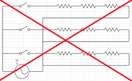
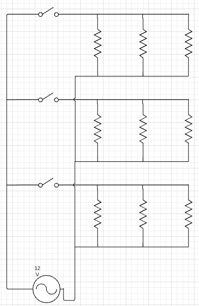
I have a 110V/12VAC (USA) transformer for common landscape lighting. We have 3 "zones" that I'd like to turn on/off as desired, two for lights (all LED at the moment) and one for a pond. My plan for now is to run a single 14ga-2 wire to a switch box, then run a line from that to each zone. (1 line in, 3 lines out) Note from the circuit that my intent is to add lamps and pumps n stuff (yes, watching the run length and load) and then cap each line at the end to return the circuit back through ground.

My questions are:

1) Is that the way this should be done?
2) I'd like to control that with a remote, in addition to, or maybe instead of using a common switch. Can someone recommend a small, elegant, and inexpensive solution? Home Automation is all the rage but I think commercial HA is still kinda new and expensive. My house is still full of cheap X10 from the 90's, which I need to start to replace. I've never done a project like this with low voltage AC remote control.
3) Perhaps to complicate this more, this is a Hampton Bay 900W transformer with 3 taps to support 300W each. I'm concerned that if I turn off two of the circuits, and maybe just run a couple fountain pumps during the day (total<50W), that there won't be enough load on the tap. How do we protect against that? I will be putting more load on the total system as time goes on, but I don't expect too much load during the day on any one tap.

Thanks!

Version 1 Version 2

6
  • 1
    That diagram is off... the middle and bottom switches close into a dead short, and you probably don't want your loads in series... Commented Sep 19, 2018 at 2:09
  • 1
    @batsplatsterson I see jumps on the middle and bottom switches. That part looks fine. Commented Sep 19, 2018 at 2:26
  • There is no connection between + and - there, note the little hop of ground over +12v lines. I only drew it like that to communicate that each line goes back to the switch box. If I put common at the end and drew down to the bottom, rather than coming back from each one, it would give the impression that there is another wire going back to the transformer. Each load is in series in its own circuit, but all of the sub-circuits are in parallel to the main. Any better? Thanks.
    – TonyG
    Commented Sep 19, 2018 at 2:29
  • Yes, you have it perfect. Except.... That's not ground, that's C. AC remember? AC low voltage is R and C, at least that's as well established as LVAC names get. and it probably shouldn't be connected to ground, which is safety earthing. Ground is not used to carrry normal current. Commented Sep 19, 2018 at 6:38
  • @Harper thanks I couldn't see those jumps before, I see them now. Commented Sep 19, 2018 at 9:37

1 Answer 1

1

Easiest question first - there's no issue underloading a power supply, so don't worry about that part of question 3.

If there are three 12V taps on the power supply, would it make sense to power each of your three circuits (I'll just say circuits rather than zones as you call them) from each of the three taps?

I don't think you really meant you'd run the return through the ground, that would be a bad idea... you want to run a two conductor wire through the circuit, and tap both conductors at each load so everything's in parallel.

You can use wireless switches like the Lutron Caseta and Pico remote or similar products to do everything you want with respect to automation - it's come a lot way since your 90's X10 stuff.

4
  • 1
    I knew someone would ask about making use of those 3 taps. :D I intend to have one tap for the back yard, another for the front, and another for "whatevah". Each of those will have a similar circuit (zone) setup with switches. I got this transformer for $50 rather than the retail $200 so it's a little overkill.
    – TonyG
    Commented Sep 19, 2018 at 2:37
  • 1
    Ahh, I understand what you were saying about making each run parallel vs serial. Yes, and rather than capping the end (where path of least resistance would lead to a short) the last load would be the terminator. Is that correct? Thanks!
    – TonyG
    Commented Sep 19, 2018 at 2:39
  • 1
    Corrected overall circuit so that each of the sub-circuit "zones" is parallel unto itself. While common could have been shown all the way to the left (and with the proper symbol), as shown this describes the actual physical layout.
    – TonyG
    Commented Sep 19, 2018 at 3:13
  • @TonyG - with the loads in series you wouldn't have a dead short - the loads are there, there is resistance - but you wouldn't have 12V across each load, the voltage would drop across each light. And if any light went out, it would be like Christmas lights - they'd all go out. New drawing looks good! Commented Sep 19, 2018 at 9:36

Your Answer

By clicking “Post Your Answer”, you agree to our terms of service and acknowledge you have read our privacy policy.

Not the answer you're looking for? Browse other questions tagged or ask your own question.