4

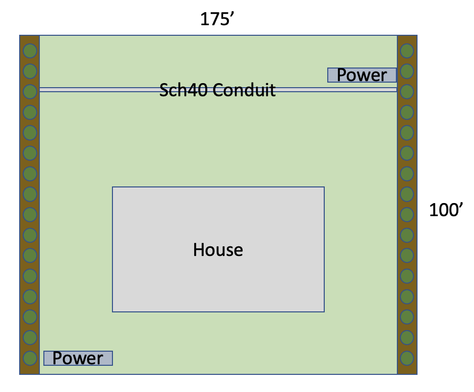
I am looking to install a new, all-LED low voltage lighting system. Basically I want to illuminate the 2 edges of my lot with 100' of 12V up lights and a few path lights. It's a pretty small system, only 171 watts with half of the wattage on either side. The problem is that the 2 sides are separated by 175'. I have Schedule 40 conduit underground between the 2, so I could run 12awg or even larger between them, if need be, to account for voltage drop.

enter image description here

Can I install a single 300W transformer to run both sides or would I need to have 2 transformers on either side of my lot to run the 12V because of the distance between the 2 sides? I've also read about people using SPDT relays to turn on a second transformer, but I'd rather only have 1 transformer if I can to simplify things.

Thanks!

UPDATE ==================

I asked this question with an oversimplification. I now realize I should have been more precise. I will update with more details, but please feel free to ignore this due to all of the confusion.

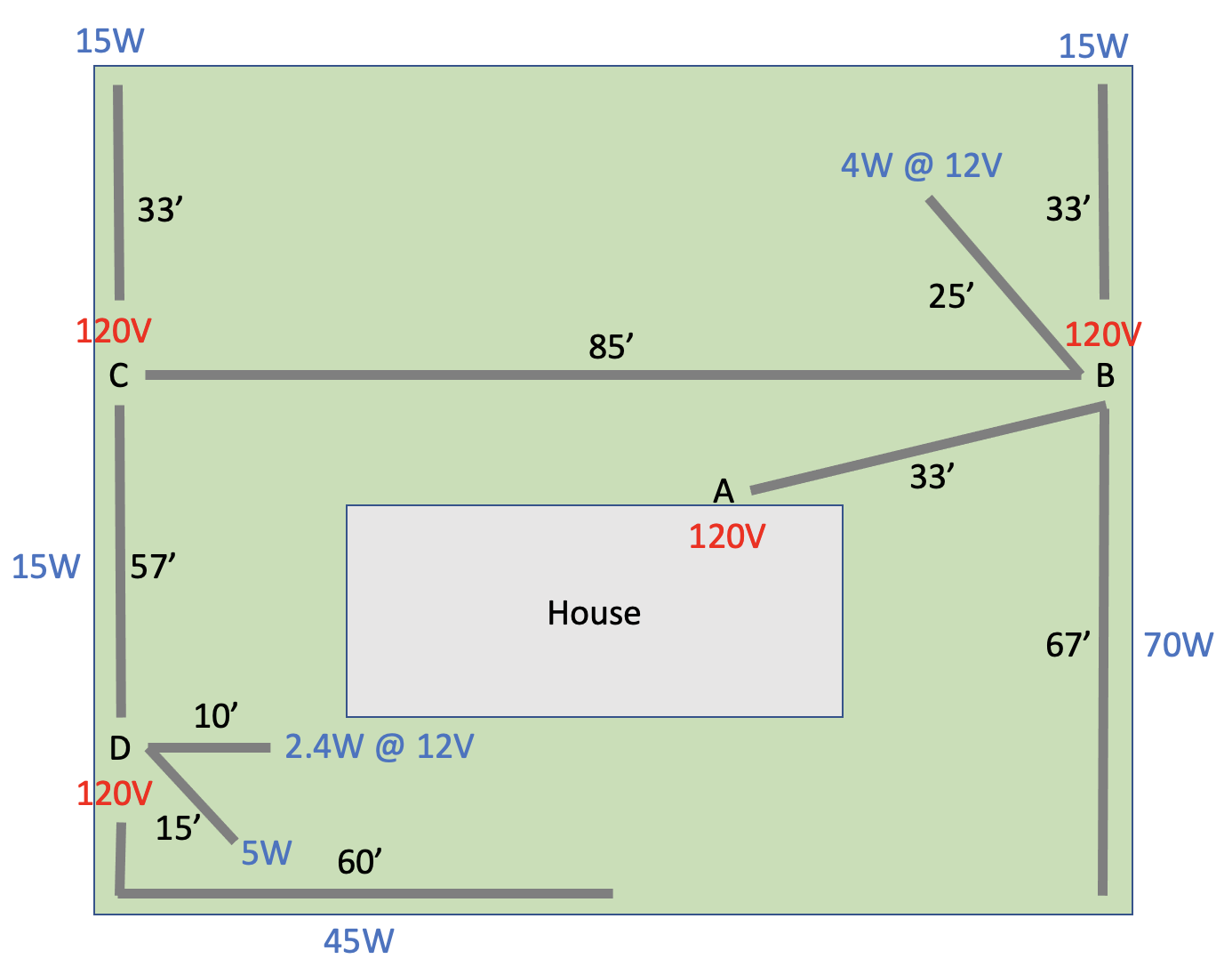
Here is the real diagram:

enter image description here

  • A is my "utility area" with irrigation setup, etc.
  • B is an underground utility box with multiple conduits
  • C is an underground utility box with multiple conduits
  • D is an underground utility box with multiple conduits at my electric meter
  • The "175'" is the sum of conduits from A->B->C->D.
  • There is 120V available at each site.

Like I said above, I should have been more precise from the beginning. My apologies, but I'm looking for how to design this low voltage system. I have some LEDs (stair lights) that must operate at 12V. I have not purchased the other lights, but the ones I am looking at are also 12V, but perhaps I could find similar 24V LED lights.

I had hoped to be able to install a single transformer at location A since that's where all of my other equipment is. Now, it sounds like that's infeasible. Could I possibly run a single transformer anywhere else (perhaps location C)?

If I'm reading the great responses I've received so far, it sounds like ideally I should have at least 2 transformers - one at B and another at D. I could link them with a relay or they could use their own photosensors.

Is there a better way here that I'm missing?

1
  • 2
    Whatever wire/cable you run through that 175' of conduit, make sure you start out with 200' of wire. You do not want a splice inside the conduit where it's inaccessible. If you end up running 120v power through there, you'd be required by code to make that splice accessible (by putting it in a junction box with an always accessible cover). I don't think the rule applies to LV DC wiring, but you don't want to pull a splice even half that distance and risk the connection coming loose meaning you'd have to pull it all back out to repair it.
    – FreeMan
    Commented Feb 15, 2022 at 15:01

3 Answers 3

3

This is an interesting distributed voltage drop problem to me, so I threw together some simulations to see what the results would be.
I've made a few assumptions about your LED lights:

  1. These are not 'dumb' LED + resistor lights, but are in fact reasonably decent LED light fixtures consisting of a constant-current power supply to drive a set of LEDs in each fixture
  2. The fixtures will run from a 'nominal' 12V supply and consume about 5W each, so if the supply drops then the driver electronics will compensate by drawing more current
  3. Each side will consist of 16 LED fixtures, with 7' of cable between them

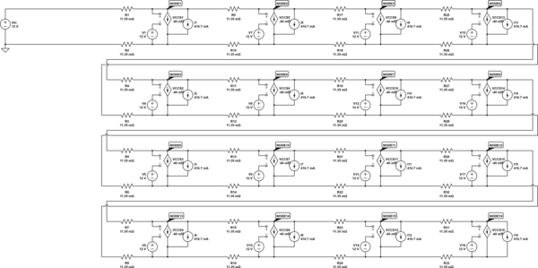
Here's an electronic circuit diagram of what one side looks like, connected 'directly' to the 12V supply through another 7' of cable, and all cables are 12AWG copper. I've modeled each LED fixture as a roughly 5W power sink:

schematic

The simulation tells me that your supply is pushing out 7.3A, and the voltage at each fixture ranges from about 11.8V at the 1st one, down to 10.5V at the end.
So if my assumptions above about your LED fixtures are correct, and these fixtures will run 'normally' from 10.5V - then 12 AWG wire is fine for the one side connected directly to the 12V supply.

Things get more interesting on the other side...

Linking them with 12 AWG copper is not going to work very well at all. That 175' of wire turns into more than 0.5 ohms of round-trip resistance, and with the increased current draw from the fixtures, the voltage arriving at the 1st fixture is already all the way down at 5.3V with your 12V supply pushing 11.8A just down that line (it's also still pushing 7.3A down the 'near' side). The poor LED fixture at the far end is only seeing a little over 3.2V - so it's almost certainly not even working ...
In actual practice in this scenario you'll probably see all kinds of weird behavior as fixtures up & down the line blink on & off as they try to start up, but as they draw current their supply voltage drops and they turn off again.

Things get a little more realistic if you bump the 175' run up to 8 AWG copper (0.224 ohms) where you'll get about 10V at the 1st fixture and 8.6V at the last one, with the 12V supply pushing out about 8.5A down to that side.
Maybe your fixtures will work at 8.6V ... maybe not ...
Note that here on the 'far' side I've still got the inter-fixture wiring using 12 AWG as it is on the 'near' side - it's only the 175' length that I've bumped up.

Bumping up again to use 6 AWG copper or 4 AWG aluminum for the 175' link helps.
This reduces the round-trip resistance of the 175' cable to under 0.15 ohms and now the 1st fixture on the far side is seeing 10.8V and the last one gets almost 9.5V.
But that's likely still scraping the bottom of the 12V nominal rating of an LED fixture and even if it works, it leaves no margin for error.

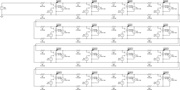
So bumping once more to 4 AWG copper or 2 AWG aluminum (as suggested by Harper already) gives you a much better result:

schematic

The round-trip resistance of the 175' cable is all the way down to around 0.09 ohms.
The 1st fixture sees 11.3V, the last fixture sees almost 10V, and the 12V supply is pushing a little over 7.6A down that leg.

If this were my decision, I'd still be a little uncomfortable with the 'almost 10V' down at the last fixture on the far side.
My preferred solution would be to supply each side independently with its own 12V 10A supply, using 12 AWG copper between each fixture. I'd probably also bump the supply voltage up slightly to 12.5V-13V just for a little extra margin.
It may not seem like much at first glance, but with a 12.5V supply, the 1st fixture on the 'near' side (all 12 AWG copper) sees 12.3V and the last fixture sees 11.1V, with the supply pushing out 6.95A.
It may seem counter-intuitive, but raising the supply by 0.5V actually increases the end-of-the-line voltage by 0.6V because there's less current being drawn and therefore less voltage dropped across the length of cable.

2
  • First off, this is an amazingly-detailed response. Thank you for it. After reading all of this, I seem to have 2 possible choices: a. use a 16AWG common wire for one side powered by the 120V on that side, run it across the 175' conduit, and use a SPDT relay to sense down to 3V to turn on the other side's transformer or b. use 2 different transformer systems / timers. Does that sound about right?
    – pennstump
    Commented Feb 17, 2022 at 19:26
  • If the 175' wire is only the signal/control wire to tell the relay at the far end to turn on or off, then there will be very little current flowing though it, and therefore very little voltage drop -so you should have no trouble operating a 12V relay on the end of that line.
    – brhans
    Commented Feb 17, 2022 at 19:36
3

It's not entirely clear whether the system is to be fed from "Power" at the lower-left, the upper-right, or both corners. The single-transformer best-case scenario is still pretty bad. I'll explain.

The plan calls for about 85 watts of power on each side. The nominal voltage is 12 so that's about 7.125 amps. If there is to be a source at one end of the 175 foot conduit and a load at the other end we can consider how much voltage will drop in crossing the 175 feet. If it is wired with 12 AWG copper the resistance of the supply and return together is about 0.56 ohms (1.6 ohms per 1000 ft times 350 feet there and back). A 7.125 amp current through 0.56 ohms incurs a drop of about 4 volts -- from the 12 volt supply, only 8 volts arrives at the first lamp. It's even worse for the lamps further down the line. If you actually built and measured it you'd find the lamps drawing less than the advertised wattage due to the low supply voltage, so the total current draw would be a bit less than figured here, so the voltage drop wouldn't be quite so bad. Still, though, there will be a significant reduction in light output compared to the side that is near the transformer. It'll be visibly dimmer.

If you used 8 AWG wire at 0.64 ohms per 1000 ft the there-and-back loop resistance through the 175 foot crossing would be more like 0.22 ohms and the voltage drop about 1.6 volts. That's a lot better, but it ignores the cost of 8 AWG copper wire and also ignores drop that will occur along the 100 foot lot line.

If it were possible to run a 24 V DC system instead of 12 V that would help significantly. As an alternative, you may need to distribute AC mains voltage to the midpoint of each lot line. With this arrangement you'd have two transformers driving four segments of 12 V system, each segment only 50 feet long and serving just 42 watts of load.

1
  • I have 120V available in both sites. I could use one or both of them to build an "optimal" solution, whatever that may be. I could use 24V for the lights, but I have some LED stair lights on both sides that can only accommodate 12V. I would have to buck the 24V down to 12V for them.
    – pennstump
    Commented Feb 17, 2022 at 19:28
2

This is a job for aluminum wire.

Mainly so you don't go broke.

#6Al has electrical characteristics similar to #8Cu, and it fits on the relatively inexpensive ILSCO "Mac Block Connectors". You can also use service panel ground rods, cut them up and hand insulate them with tape.

#2Al is also a "pricing sweet-spot".

Take voltage drop very seriously. Don't "do the bamp".

There's a thing I call the "bamp" which is done by the inexperienced, including most homesteaders on Youtube. They're doing a low-voltage project. It's a long distance, so they know something matters about voltage drop, but they don't know what to do about it exactly. So they take the normal wire size they would use if they were going 2 feet, and "do a wire size bamp" to the next size up. They don't crunch any numbers to see if that size is workable. Later their project fails, and they blame the technology. "I did the bamp!"

You actually need to do a voltage drop calculation. Now you can look up the "resistance per 1000'" of the wires, divide by your distance (remember you need to compute on round trip!) and Greg Hill's answer walks you through that. Or you can use any of the "voltage drop calculators" on the Web - that's what I do.

The most important thing you can do is flip the switch from "copper" to "aluminum". (or, take the copper number, subtract -2 numerical wire sizes and that's close to the aluminum figure).

Let's say you have power on one corner. 7.1A load for the whole 100' side. However halfway down the side, the load is down to 3.5A. You really ought to compute it segment by segment, but if you just toss in 100' and 3.5A to the voltage drop calc, you get 10% voltage drop with #12 copper. Or 6.1% with #10 copper.

Unfortunately that will severely dim LED lighting if the LEDs simply use resistors to regulate and do not have a switching regulator.

For the 175' lateral, you are probably best off using #2 aluminum, which will give just under 4% voltage drop for the 175' lateral. That will be added to the voltage drop down the line. You could also use 6-6-6-6 aluminum (4-conductor) and parallel two conductors (not technically legal, but this is 12V outdoors for Pete's sake, what are we going to do, set the dirt on fire?) at which point you'd have 4.51% drop for the lateral until one of the parallels fails, and then 9.02% drop. Well within thermal limits (solo #6AL is good to 50A) but obviously more voltage drop. Mind you this lateral drop is added to the down-the-side drop discussed in the last paragraph.

I would probably use copper down the sides, and aluminum on the laterals. That way you're just using common landscaping hardware instead of having to figure how to do 20 aluminum splices one at each lamp.

Your Answer

By clicking “Post Your Answer”, you agree to our terms of service and acknowledge you have read our privacy policy.

Not the answer you're looking for? Browse other questions tagged or ask your own question.