5

Talking with an electrician some time back when the house was being remodeled we were discussing the virtues of the remote control of lights. He had boasted that while the technology is neat, there are some things that just don't work well unless you wire them traditionally.

The example that he had used was a light house. On the ground level, you flipped the switch, and the light at that level and one floor higher in the stairs went on. When you got to the second floor and flipped the switch there, the light on the ground floor went off, and the light on the third floor went on. And so on and so forth up the tower - each flip of the light switch turned on the light above and turned off the light below as you went up. When you went down, throwing the switch would turn off the light on the floor above, and turn on the light on the floor below.

Now, I could probably do it in today's world by spending a boatload on hue taps and lights (it wasn't feasible at all in the x10 days - and I don't think that technology would work at all), but the classical approach still eludes me.

So, how does the wiring that the electrician work? What is the arrangement of switches that facilitates this?

4
  • Quite feasable with X10 if you separate the input device from the light controller and run the signals thru X10's, or anyone else's, home-automation controller to apply a bit of logic. Ditto any other smart-switch system.
    – keshlam
    Commented Feb 3, 2016 at 16:30
  • @keshlam that requires a different system for logic and isn't in the wiring itself. And if you were to do that, a relay system with rocker switches would probably work better. The hue (a system I'm more familiar with) has the advantage of each switch sets a scene for certain lights... though I'm not sure how well that would work for two people on the stairwell at different places. At the time of this conversation, the hue didn't exist, X10 was state of the art and home automation was nascent.
    – user1405
    Commented Feb 3, 2016 at 16:46
  • With the macro processor, it can handle the "this on, others off" behavior.It's certainly not a hardwired solution; I mention it only because the electrician seemed to think this was something only old-style switches could do.
    – keshlam
    Commented Feb 3, 2016 at 16:51
  • @keshlam in the late 90s, there weren't as many controllers (though I could be proven wrong). I believe there are also some other issues with it (like turning off the light where you are standing for a command cycle). And has the added problem of going up and down cleanly (you would need to have three lights on). That said, I'm not too interested in that because its rather 'easy' today to do with existing home automation systems (I've been looking at touch screen case Raspberrys with a custom lighting control for hue as an option for light switches).
    – user1405
    Commented Feb 3, 2016 at 17:00

3 Answers 3

2

Assume we have 6 switches (S1-S6) and 5 lamps (L1-L5) -- also assume that we don't want any lights in the stairs on when the stairs are not in use by anyone (even if there's someone on top of the tower), and that someone walking up the final flight of stairs doesn't want the light below them on. Finally, we can assume that nobody's flipping light switches in the middle of this sequence -- if they do, the behavior's unspecified (although it won't kill you or burn out any lightbulbs).

This gives us a truth table that looks like so, assuming that the switches and lights are numbered from bottom-most to top-most:

S1  S2  S3  S4  S5  S6    L1  L2  L3  L4  L5
OFF OFF OFF OFF OFF OFF   OFF OFF OFF OFF OFF
ON  OFF OFF OFF OFF OFF   ON  ON  OFF OFF OFF
ON  ON  OFF OFF OFF OFF   OFF ON  ON  OFF OFF
ON  ON  ON  OFF OFF OFF   OFF OFF ON  ON  OFF
ON  ON  ON  ON  OFF OFF   OFF OFF OFF ON  ON
ON  ON  ON  ON  ON  OFF   OFF OFF OFF OFF ON
ON  ON  ON  ON  ON  ON    OFF OFF OFF OFF OFF

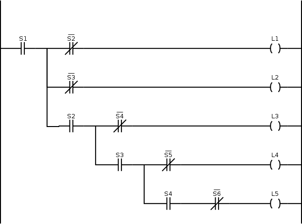
This then leads us to the classical industrial automation world! While in houses, light switch wiring is generally limited to single, 3-way, and 4-way patterns -- there is nothing (Code or otherwise) that prohibits more complex configurations of light switches provided the neutral wire is unbroken. In other words, you can use light switches to implement ladder logic in much the same way that an industrial control panel would be designed back when all you had to do it with was a bucket of switches and relays.

For our case, this results in a fairly simple ladder diagram that looks like the one below.

Ladder diagram of this mess o' switches

Given that true DPDT (note: not 4-way) general-use snap switches are a standard item that can be ordered in through any electrical supply house (if you can put up with having to tell people not to leave the switch in the center position, that is), and that you only need to run what amounts to two travelers between the switches provided you feed the power in at the bottom switch, this is eminently implementable.

There is a caveat to this, though -- because of the assumption that nobody's flipping switches in the middle of this sequence -- the second guy to come up the stairs isn't going to get the results he wants. You'll need additional logic (and perhaps some relaying) to do that -- this would be a good exercise for the reader.

4

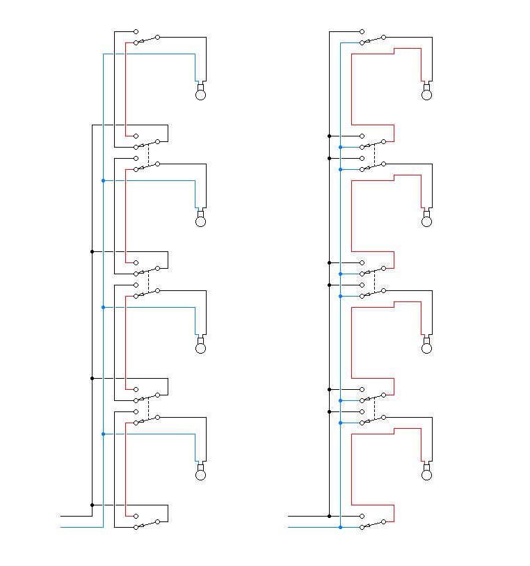
As Wolf says, a combination of SPDT and DPDT switches. One switch on each floor, top and bottom are SPDT, all others are DPDT. The number of switches is one more than the number of lights. Here are a couple of ways to wire it:

Lighthouse tower stairwell wiring

The left diagram shows the sane way. Blue is the neutral leg.

The right diagram shows how to use the Carter three-way pattern to save copper. I think this is now banned throughout the civilized world because sometimes when a lamp is off it is hot on the shell side. It requires turning off the entire circuit at the service panel to safely change a light bulb.

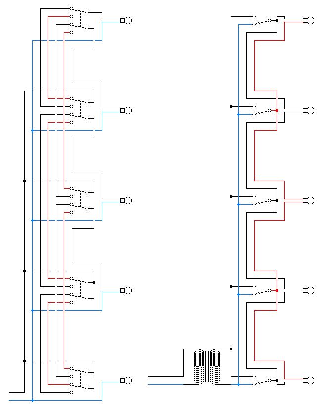
EDIT 2/4/16: The actual requirement is for two lamps to be controlled by each switch. I think that the stairway should be usable serially in the same direction (the accepted answer only allows descent after ascent). Here are a couple of ways to wire it:

Private building stairwell wiring

The left diagram shows the safe way. Blue is the neutral leg.

Note that, except for the lowest and highest floors, it is not possible to control a lamp on the same floor as the switch. I'm sure this can be done with an additional switch on each floor. However the instructions for using the switches will become too confusing for most users. And I am drifting away from the core subject of this SE.

The right diagram shows the functionality of the left diagram, implemented in the Carter system. Note the remarkably reduced number of wires and switch contacts. Remember, this method is very dangerous. You might get electrocuted maintaining it, you might lose your license for building it, and you might get downvoted just talking about it.

This pattern, and other too-clever circuit solutions, often find application in low-voltage, signalling, and railroad block controls. It is not used in residential structures, which are typically required not to kill their occupants.

6
  • That's very neat, what program did you use to create the diagram? Although, again it still doesn't work as in the example. If you cut the first floor switch on, it does not turn on the second floor at the same time. However, I think it's almost there as the rest matches up.
    – TFK
    Commented Feb 3, 2016 at 13:53
  • @TFK: You are correct. I did not read the problem statement carefully. The OP seems to be picturing an installation with lights on each floor, whereas I have placed the lights in the stairwell between the floors. My solution turns on exactly one light at a time. You are saying the requirement is for exactly two lights at a time. Commented Feb 3, 2016 at 18:22
  • Unfortunately -- you should drop the right diagram as you're getting a -1 for it from me. (It's called a Carter 3-way by the way, not a Coast/California 3-way which is an entirely different beast that has no involvement with the neutral, but doesn't scale to 4-way apps) Also -- 4-way/changeover switches are not the same as a true DPDT switch, which is what's needed in the left diagram. Commented Feb 4, 2016 at 2:16
  • @ThreePhaseEel - You're correct, it's Carter not California. Also note that Wolf said ganged 3-way aka DPDT; I'm the one who incorrectly called that a four-way. I'm correcting my answer. However - I'm leaving the right-hand diagram posted, as it is clearly marked as banned throughout the civilized world. The OP is clearly not planning to rough in the wiring in a multistory tower so I think it is safe to show the diagram. Commented Feb 4, 2016 at 4:15
  • As TFK said, that's very neat. Could you please tell us what program you used to make those drawings? Commented Feb 5, 2016 at 3:28
0

Sounds like 3-way switches. Two of them, ganged together so they throw on the same physical switch handle. It's like a single 3-way is SPDT, 2 ganged 3-ways is DPDT.

So, 1st floor lighting controlled by 1st floor and 2nd floor. 2nd floor lighting controlled by 1st floor and 3rd floor. 3rd floor: 2nd and 4th. Etc.

1
  • That would work for one floor only if you used two DPDTs as 3-ways. Trying to tie in additional floors would require connecting to the last switch though so that the floor before it would be shut off. At this, if you cut the switch on the first floor back on, it'd cut on the first, second third, etc. I think it's possible, but not with just DPDTs.
    – TFK
    Commented Feb 3, 2016 at 13:43

Your Answer

By clicking “Post Your Answer”, you agree to our terms of service and acknowledge you have read our privacy policy.