2

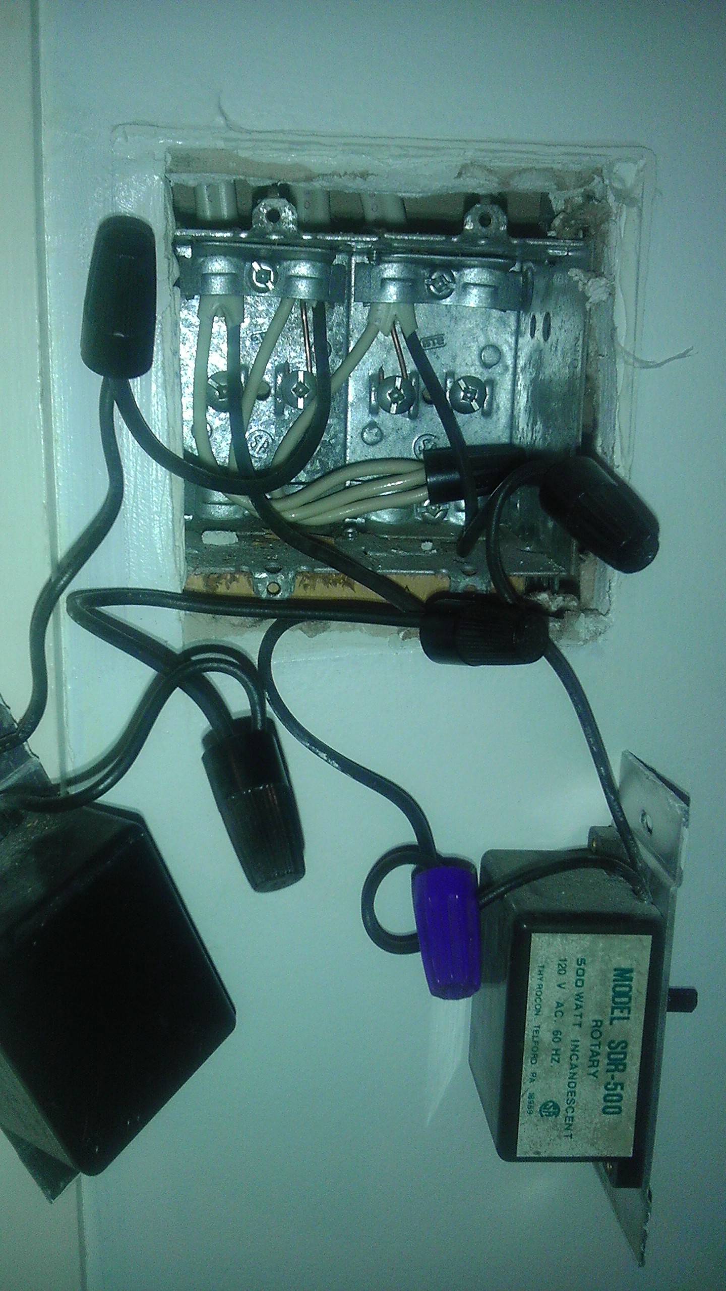
I'm planning to replace two dimmer switches -- but I found the following clever wiring when opening up the junction box. Three circuits where the neutral lines are spliced together, one live line spliced to two switches, and the remaining two live lines going to the respective switches (photo below).

I'm tempted to just replace the switches and keep the wiring the same, but this looks very dubious! Is my concern warranted, and if so, how should I correct the problem?

dubious wiring

2 Answers 2

4

This is one single branch circuit, and a very common wiring method.

I've highlighted the ungrounded (hot) conductors in your image, to help you understand what's going on.
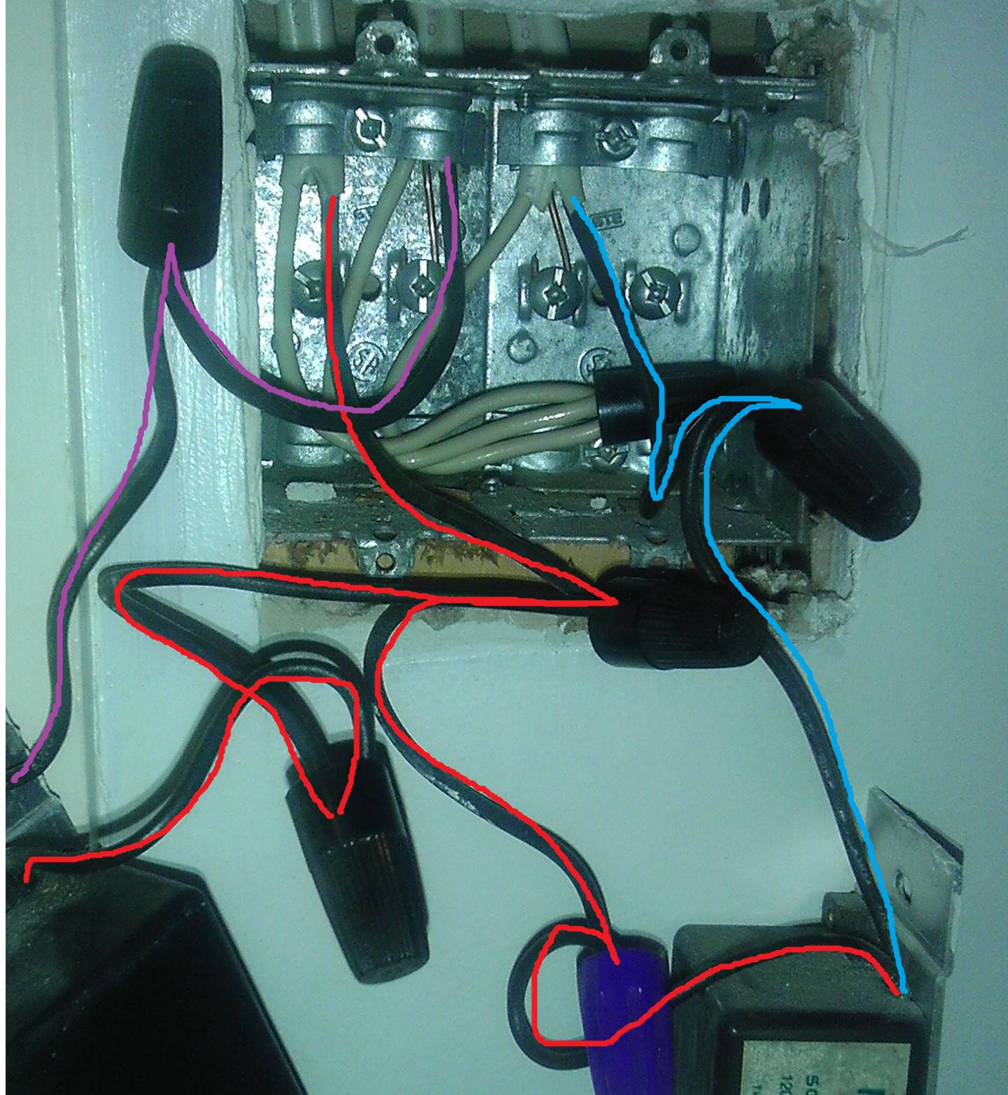
Highlighted image

The wires highlighted in red, represent the feed coming to the box from the panel. These wires are split, so as to provide power to both switches. If you were to measure between any of these wires and ground (or neutral), you'd get ~120 volts.

The wires highlighted in purple, are taking power from one of the switches (dimmers) to the load (light). If you measured from these wires to ground (or neutral), you'd get ~120 volts only when the switch was in the ON position.

The wire highlighted in blue is similar to the purple wire, except that it takes power to a different load (light).

All the white grounded (neutral) wires are connected together, to complete the circuit back to the panel.

If you followed the electricity through the circuit, it would go something like this (though not really since it's alternating current).

  • The electricity flows in on the red wires to both the switches.
  • When the switch is turned ON, electricity flows out through the purple or blue wire (depending on which switch is on).
  • The electricity powers the load (turns on the light, presumably).
  • The electricity then comes back to this box on the white wire.
  • Finally the electricity flows back to the panel on the white wire that's bundled with the red wire.

As David Tweed pointed out, I'm not sure why there are so many twist-on wire connectors in use.
1
  • Thank you for explaining what is depicted in the photo. I haven't worked with switch connections often enough to see this type of connection, but it makes perfect sense now. Usually I work with the load end, which is much simpler :) Commented Jun 14, 2015 at 15:13
4

That isn't three circuits, it's only two. The Romex on the left is the power coming in from your distribution box, and the other two are your two loads. Each switch is connected between the incoming power and one of the loads.

I'm not sure why there are so many wirenuts on the supply side — it seems that if one wirenut can connect three wires, then one should be all you need. Get rid of the extra pigtails.

6
  • Maybe the wires from the dimmer switches are stranded and the original installer had some trouble conceiving how to wire nut two stranded wires to a solid wire. Just a thought.
    – Michael Karas
    Commented Jun 13, 2015 at 16:35
  • @MichaelKaras: Maybe, but that still doesn't explain the blue wirenut, which appears to be connecting two stranded wires together.
    – Dave Tweed
    Commented Jun 13, 2015 at 17:20
  • We can can only guess that the blue wire nut is joining two stranded wires together. The photo is fully up to interpretation in this regard. My comment was based on experience of dimmer switches having stranded wires coming out of them.
    – Michael Karas
    Commented Jun 13, 2015 at 18:01
  • Thank you for pointing out the power source -- not sure why I didn't consider that! The dimmer switches have hard-wired stranded wires which aren't removable. I suppose we could simplify and remove the blue and lowest black wire nut, and join those connections to the center nut. In any case, the connections are much simpler now that standard single-pole switches are in the junction box. Commented Jun 14, 2015 at 15:20
  • 1
    @MichaelKaras My guess would be that originally the wires were pigtailed to switches, then at some point dimmers were added. Whoever installed the dimmers just connected the leads to the wires that were connected to the switches, instead of removing them and making the connection with a single twist-on connector.
    – Tester101
    Commented Jun 14, 2015 at 16:00

Your Answer

By clicking “Post Your Answer”, you agree to our terms of service and acknowledge you have read our privacy policy.

Not the answer you're looking for? Browse other questions tagged or ask your own question.