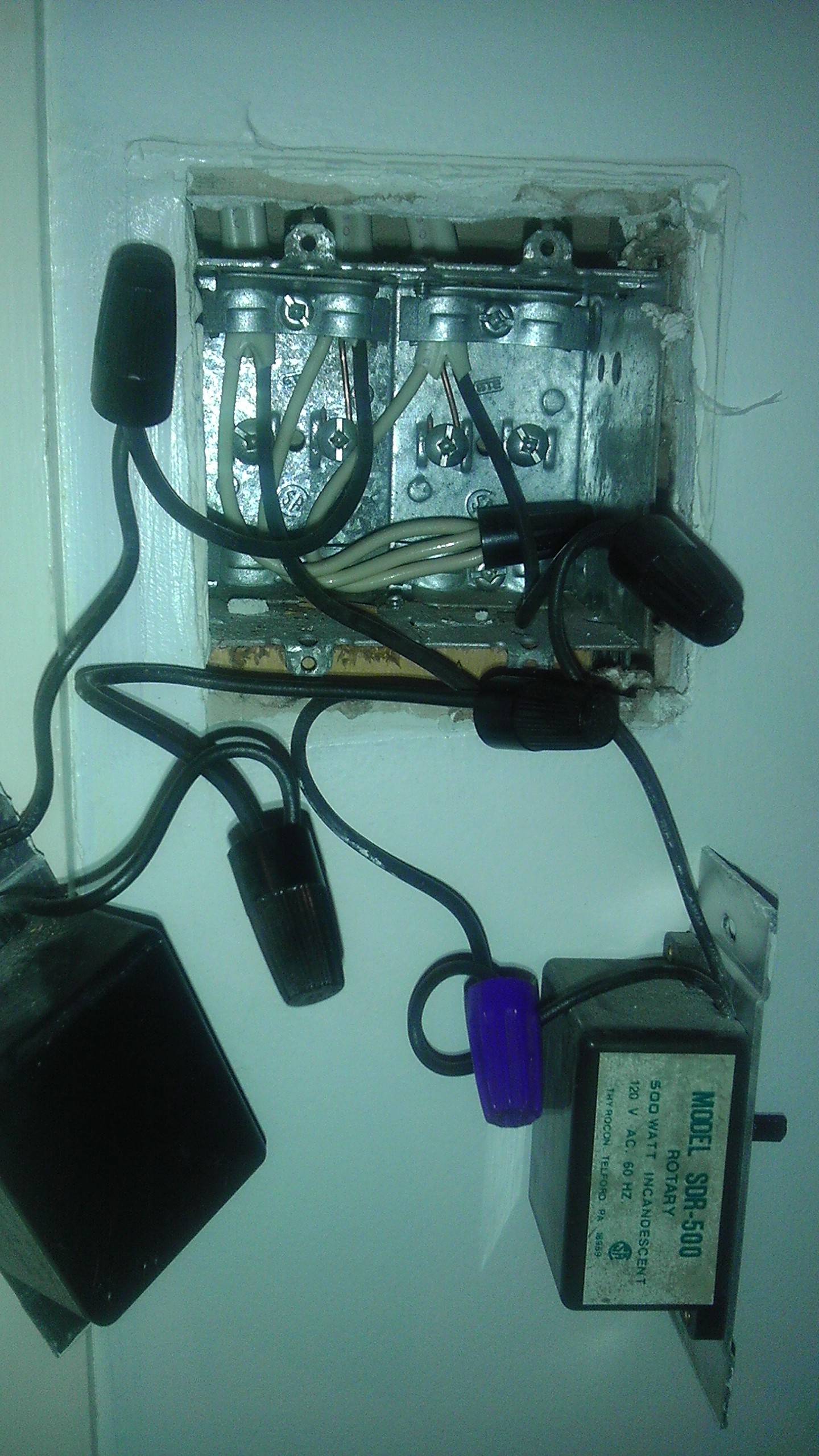
This is one single branch circuit, and a very common wiring method.
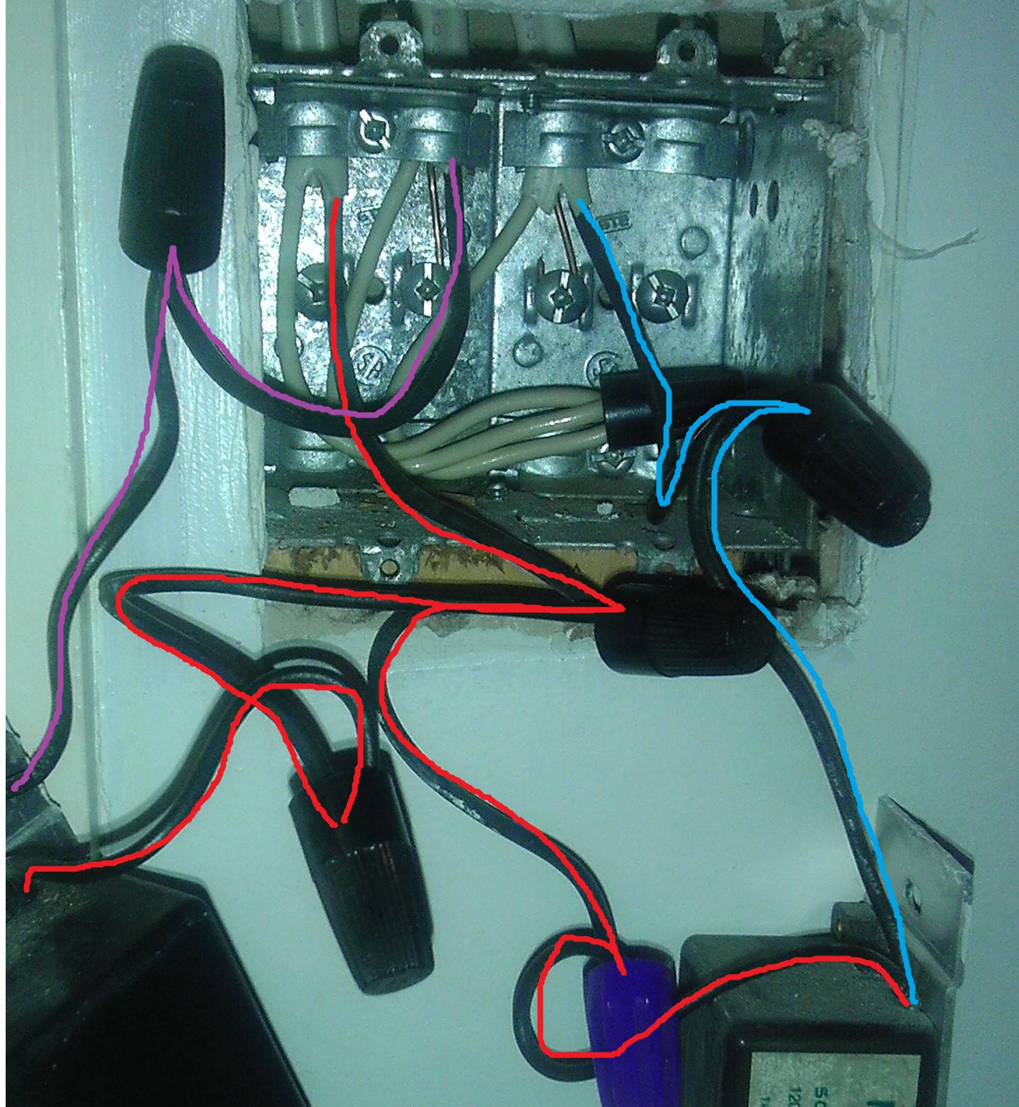
I've highlighted the ungrounded (hot) conductors in your image, to help you understand what's going on.

The wires highlighted in red, represent the feed coming to the box from the panel. These wires are split, so as to provide power to both switches. If you were to measure between any of these wires and ground (or neutral), you'd get ~120 volts.
The wires highlighted in purple, are taking power from one of the switches (dimmers) to the load (light). If you measured from these wires to ground (or neutral), you'd get ~120 volts only when the switch was in the ON position.
The wire highlighted in blue is similar to the purple wire, except that it takes power to a different load (light).
All the white grounded (neutral) wires are connected together, to complete the circuit back to the panel.
If you followed the electricity through the circuit, it would go something like this (though not really since it's alternating current).
- The electricity flows in on the red wires to both the switches.
- When the switch is turned ON, electricity flows out through the purple or blue wire (depending on which switch is on).
- The electricity powers the load (turns on the light, presumably).
- The electricity then comes back to this box on the white wire.
- Finally the electricity flows back to the panel on the white wire that's bundled with the red wire.
As David Tweed pointed out, I'm not sure why there are so many twist-on wire connectors in use.


