0

I opened up my switch box and forgot to mark off which wire was connected to which wires on my dimmer before I removed it. Now I want to put that dimmer back but I don’t remember what wires connected.

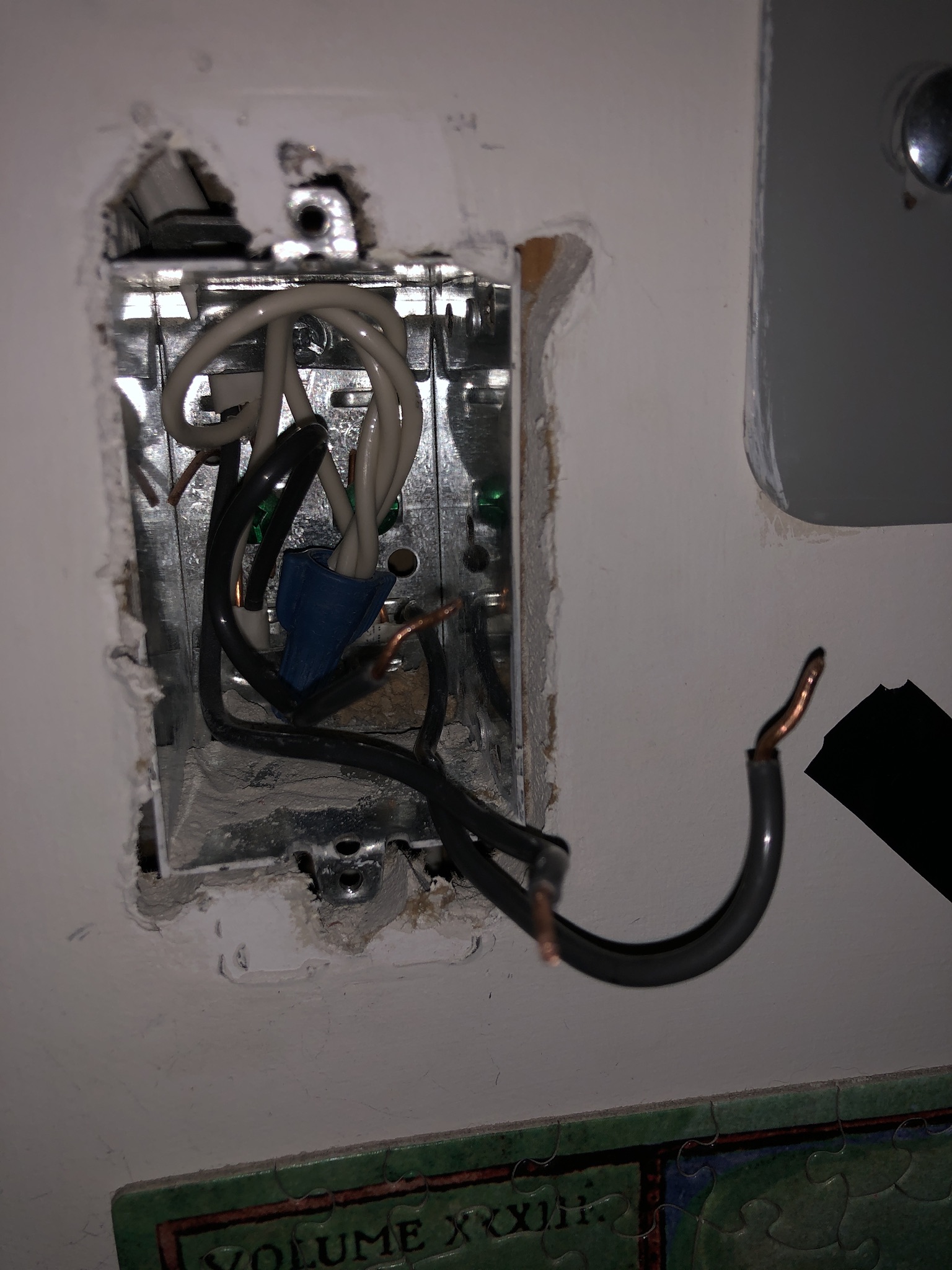
Inside the switch box I see 3 dark grey wires that don’t have any markings on them. I’m having difficulty figuring out what each wire does. Each seems to be coming out of a different spot. Could anyone help me out?

enter image description here

9
  • Any thing would just be guessing right now. With just that box without knowing which wire goes where, about the only guess is to see if the position of the wires matches up with the switch screws. This is bad guessing since those wires were probably moved.
    – crip659
    Commented Mar 1, 2023 at 21:28
  • That wiring is not proper for 3-way switches. It's not even improper/illegal for 3-way switches. It must be wired as a plain switch, with the "dimmer" being a smart switch talking via radio or powerline signaling to the other switch. Commented Mar 1, 2023 at 21:36
  • 1
    What would be your suggestion if it wasn’t a 3 way? I might be wrong about that @keshlam Commented Mar 1, 2023 at 22:10
  • 2
    @manassehkatz-Moving2Codidact's answer parallels my comment, so I don't think I need to write one...
    – keshlam
    Commented Mar 1, 2023 at 22:27
  • 1
    No prob Great minds think alike; so did ours.
    – keshlam
    Commented Mar 2, 2023 at 0:10

2 Answers 2

1

An ordinary set of 3-way switches consists of 2 switches, with one switch connected to the incoming hot, one switch connected to the switched hot, and a 3-wire cable going between them with 2 of the 3 wires connected to both switches as travelers and the third wire one of:

  • Neutral
  • Hot
  • Switched Hot

depending on design.

There are also some ways to wire "3-way" switches using smart switches where there are only two wires between the switches, or the switches aren't even connected at all, with one of them being either a line-powered (so needs power but not necessarily same circuit as the other switch) or battery-powered switch.

Based on the picture and description, this is most likely not a 3-way setup.

Assuming it is a regular single dimmer switch with three cables, there are a few ways to wire it up. But we can pretty much rule out "old style two wire switch loop" because typically with those you only see one cable in the switch box. Which means the likely setup is:

  • One cable coming in from the panel (or earlier in the circuit) with hot and neutral
  • One cable going to the light fixture with switched hot and neutral
  • One cable going to another switch or receptacle or other device

To figure this out:

  • Carefully separate all the black wires
  • Turn on the breaker
  • Use a non-contact voltage meter and/or a multimeter to determine which wire is hot. Only one should be hot when the wires are disconnected. If you find more than one hot (NCVT detects voltage and/or multimeter shows ~ 120V between wire and ground/metal box) then STOP.
  • Turn off the breaker. Mark the hot wire so you know what's what.
  • Connect the hot wire to one of the other black wires.
  • Turn on the breaker and see if the light goes on. If it does, that is the switched hot. Turn off the breaker.
  • If you didn't yet find the switched hot, connect the other black wire to the hot wire and turn on the breaker to test it.
  • If you have identified switched hot, you are nearly done. If not, STOP.
  • The remaining black wire is ongoing hot to something else. There is almost certainly something else in your house currently not working...

Unless you had a hard STOP above (in which case describe what happened and we'll try to help):

  • Connect hot and ongoing hot together with a short piece of 12 AWG (if 15A or 20A circuit breaker) or 14 AWG (if 15A circuit breaker) black wire using a wire nut. Connect the other end to the dimmer. If the dimmer has two "whatever" connections then pick one. If one is labeled "hot" or "line" or "in", that's where this wire goes.
  • Connect switched hot to the other end of the dimmer. If the dimmer has two "whatever" connections then just use the one you didn't use before (obviously). If one is labeled "load" or "switched" or "out", that's where this wire goes.

If you want to install a new switch that requires neutral, you get that by removing the blue wire nut from the white wires and adding a new short piece of white wire (12 AWG or 14 AWG as above) and putting on a wire nut and connecting the other end of the white wire to your switch "neutral" screw.

5
  • So far I’ve discovered the hot wire and the wire that is connected to the light. For the remaining wire, I got to this point in your message that I need some clarification about: “Connect hot and ongoing hot together with a short piece of 12 AWG (if 15A or 20A circuit breaker) or 14 AWG (if 15A circuit breaker) black wire using a wire nut. Connect the other end to the dimmer. If the dimmer has two "whatever" connections then pick one. If one is labeled "hot" or "line" or "in", that's where this wire goes”. Could you please explain what you mean by “connect the other end to the dimmer”? Commented Mar 3, 2023 at 1:33
  • Do you mean to connect the hot, ongoing hot, and dimmer line all together under one nut? Commented Mar 3, 2023 at 1:59
  • You cut a short piece (~ 6") of black wire and strip each end. One end goes in a wire nut together with the hot and ongoing hot wires. The other end goes to the dimmer. Here (selected at random from a Google search) is an example of using pigtails to connect a receptacle - same idea. youtube.com/watch?v=UGWRijiQpQc Commented Mar 3, 2023 at 2:04
  • Is there a reason the previous electrician didn’t pigtail these wires when he installed the dimmer previously? How would he have done it without? Commented Mar 3, 2023 at 2:20
  • (a) they might have used a switch which could handle two wires under the screw ("screw to clamp"), (b) they might have put one wire in a "backstab" and one under a screw, (c) they might have put two wires under a regular screw, which is wrong. And might not have been an electrician - i.e., not trained and didn't come here to ask questions. Commented Mar 3, 2023 at 2:53
-2

I would start with the assumption that there's one hot coming in, and two going out (one to the light, one to another room or outlet).

With the wires as they are in the photo, or perhaps capped with wire nuts, you can temporarily turn on the circuit breaker.

Using a multi-tester, check for voltage between the metal box and each wire. One of them should read about 120 VAC.

Label the hot wire.

Be careful not to touch the bare wires (wear gloves).

For extra safety, turn off the circuit breaker then apply a wire nut to the hot wire and one of the other wires to connect them. If the light turns on with the breaker, you've found the wire that goes out to the light.

As for tracing the 3rd wire, this could be a process of elimination by checking which other outlets don't work with that wire disconnected.

When you've identified all 3 wires, turn off the circuit breaker.

4
  • Being careful not to touch the bare wires (wear gloves) you can safely apply a wire nut to the hot wire and one of the other wires to connect them. When the light turns on, you've found the wire that goes out to the light. No! As tempting as it may be, that is not advisable. The proper procedure is to turn off the breaker between tests - off, connect, on/test, off again. There are appropriate gloves, but a typical DIY will not have gloves that are actually appropriate for doing this type of task. In fact, in a quick search actual rated (500V 00 class) gloves are on the order of $80+. Commented Mar 2, 2023 at 15:57
  • Ordinary work gloves are not appropriate and, more importantly, do not provide safety. In fact, they can be a double problem by giving the perception of safety yet restricting movement - the first thing you want to do if you get zapped is to move away from the source. Commented Mar 2, 2023 at 15:58
  • I've never in my life heard someone say not to wear gloves when doing electrical work. I think we have to disagree on this one. Commented Mar 2, 2023 at 16:03
  • When everything is off, work gloves are fantastic for protecting your hands from scrapes and cuts. My problem is with working with non-rated gloves when the power is on. Your typical DIY (we have seen some exceptions here who have a full complement of protective equipment, but they are the exceptions) does not have electrical safety/insulated gloves - they have ordinary work gloves. (I have several pairs of work gloves of various types, I don't have electrical safety/insulated gloves - I double-check to make sure power is off before working with bare wires.) Commented Mar 2, 2023 at 16:05

Your Answer

By clicking “Post Your Answer”, you agree to our terms of service and acknowledge you have read our privacy policy.

Not the answer you're looking for? Browse other questions tagged or ask your own question.