THE BACKGROUND I have a light fitting which takes two T5 fluorescent tubes. I have purchased LED replacements which are supposed to be a direct replacement. The documentation that came with the lamps claimed that removal of the ballast was recommended (for efficiency reasons) but not required. So the first thing I did was to simply replace the tubes to check everything was working. Unfortunately, whilst the LED replacements did "work", they flickered and buzzed. So I made an assumption that the ballast would have to be removed and the LED lamps wired directly to the switched mains.
THE QUESTION The T5 lamp has four connections - two at each end. And so now the question is - how should the LED lamps be wired? The instructions for the T5 replacement lamps provides a wiring diagram. But, unhelpfully, this diagram provides insufficient information. Perhaps it makes sense to somebody who already knows how to wire the lamp, but it does not make sense to someone who doesn't know.
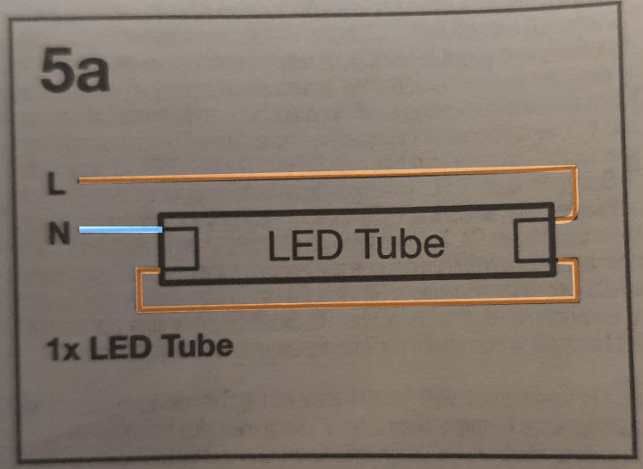
Here is the wiring diagram as it exists in the manual:
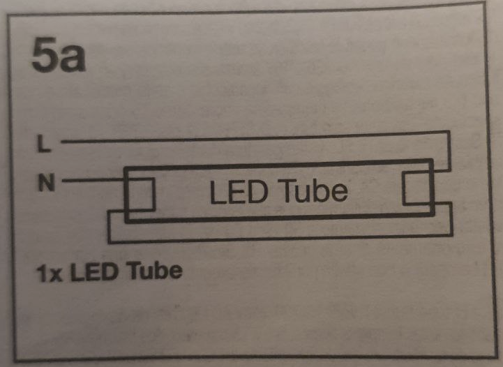
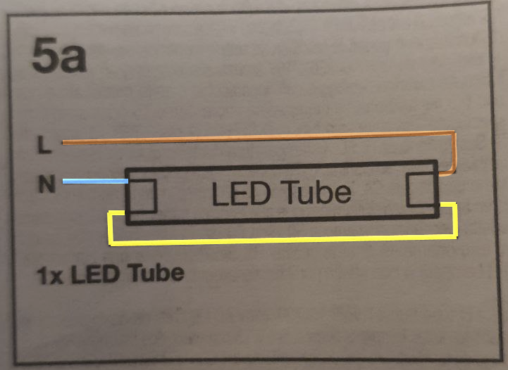
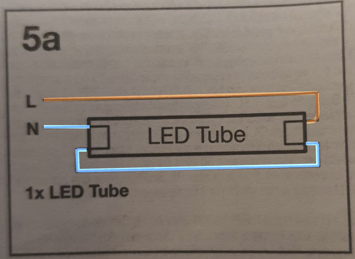
Now, to me, there are three ways to interpret this diagram. As follows below. I don't offer these interpreations as likely to be correct, I simply state them as being unclear in my opinion from the supplied diagram.
A neutral wire (blue) connects to one end of the lamp. Then another wire (yellow) shorts the bottom sides of the lamp at each end. And then a live wire (brown) connects to the remaining connection.
Neutral connects to both ends of one side of the tube, and one side of the other:
Live connects to both ends of one side of the tube, and one side of the other:
Now you might say that interpretations 2 and 3 are a bit silly. Except that I stuck a lamp on my multimeter and it shows that on one end of the lamp the two pins are shorted. Which means that interpretation 1 has the effect of interpretation 2 or 3, depending on which way around the lamp is installed.
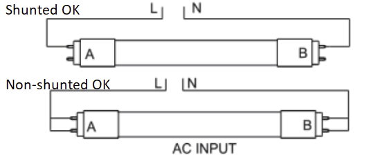
So I did some googling, hoping to find a standard pinout for a T5 lamp connection which might help me figure out the proper connection. I didn't find a pinout, but I did find information elsewhere about the wiring of these lamps. And it offers a diagram which to me would make perfect sense, except that it is not in any way implied by the diagram I was supplied with the actual lamps. I don't know what "shunted" vs "non-shunted" is supposed to mean in this diagram, but the idea that live goes to one end and neutral to the other does at least appear sensible.
But all of this leaves me with absolutely no idea how these lamps should be wired!
Can someone who is familiar with these clarify it?

