2

THE BACKGROUND I have a light fitting which takes two T5 fluorescent tubes. I have purchased LED replacements which are supposed to be a direct replacement. The documentation that came with the lamps claimed that removal of the ballast was recommended (for efficiency reasons) but not required. So the first thing I did was to simply replace the tubes to check everything was working. Unfortunately, whilst the LED replacements did "work", they flickered and buzzed. So I made an assumption that the ballast would have to be removed and the LED lamps wired directly to the switched mains.

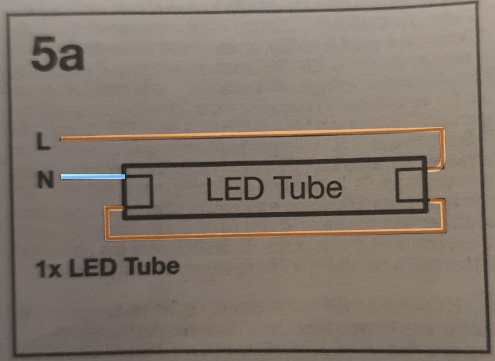
THE QUESTION The T5 lamp has four connections - two at each end. And so now the question is - how should the LED lamps be wired? The instructions for the T5 replacement lamps provides a wiring diagram. But, unhelpfully, this diagram provides insufficient information. Perhaps it makes sense to somebody who already knows how to wire the lamp, but it does not make sense to someone who doesn't know.

Here is the wiring diagram as it exists in the manual: Manual wiring diagram
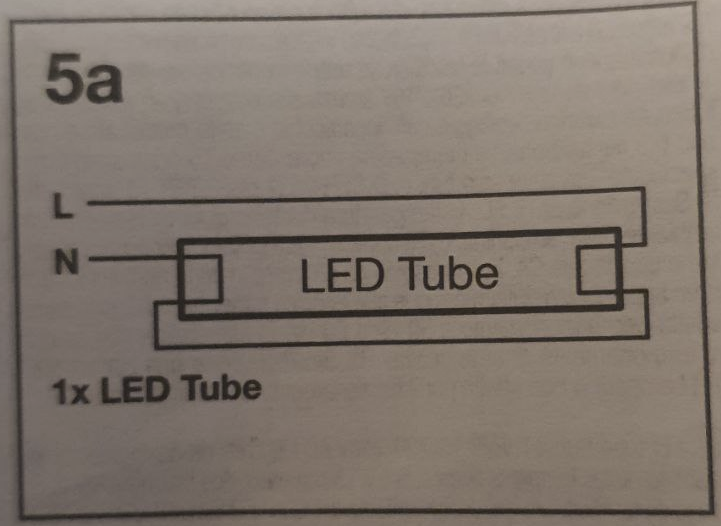
Now, to me, there are three ways to interpret this diagram. As follows below. I don't offer these interpreations as likely to be correct, I simply state them as being unclear in my opinion from the supplied diagram.

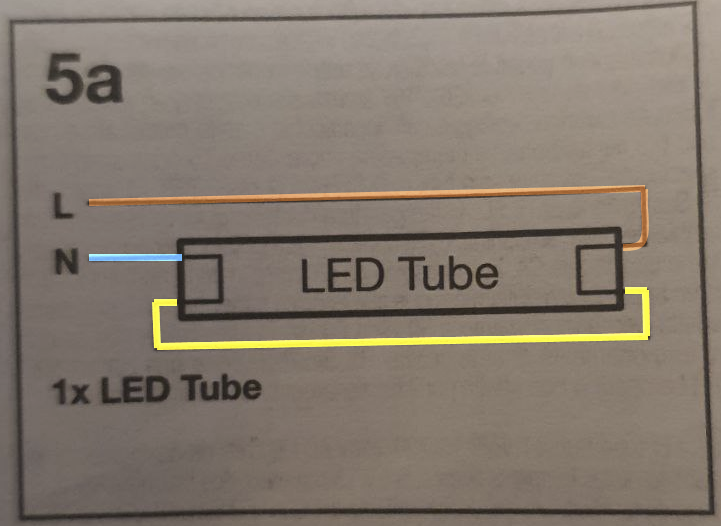
  1. A neutral wire (blue) connects to one end of the lamp. Then another wire (yellow) shorts the bottom sides of the lamp at each end. And then a live wire (brown) connects to the remaining connection. Interpretation 1
  2. Neutral connects to both ends of one side of the tube, and one side of the other: Interpretation 2
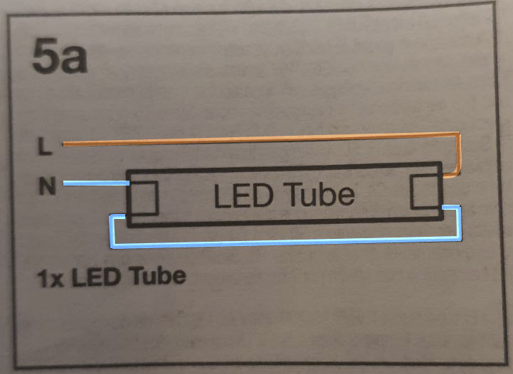
  3. Live connects to both ends of one side of the tube, and one side of the other: Interpretation 3
Now you might say that interpretations 2 and 3 are a bit silly. Except that I stuck a lamp on my multimeter and it shows that on one end of the lamp the two pins are shorted. Which means that interpretation 1 has the effect of interpretation 2 or 3, depending on which way around the lamp is installed.

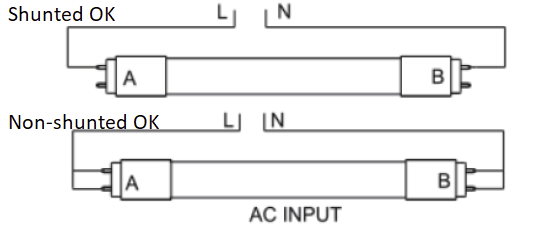
So I did some googling, hoping to find a standard pinout for a T5 lamp connection which might help me figure out the proper connection. I didn't find a pinout, but I did find information elsewhere about the wiring of these lamps. And it offers a diagram which to me would make perfect sense, except that it is not in any way implied by the diagram I was supplied with the actual lamps. I don't know what "shunted" vs "non-shunted" is supposed to mean in this diagram, but the idea that live goes to one end and neutral to the other does at least appear sensible.

But all of this leaves me with absolutely no idea how these lamps should be wired!

Can someone who is familiar with these clarify it?

enter image description here

4 Answers 4

5

That is dangerous. Do not wire a fixture like that.

I seriously doubt the quality of this product.

Generally, the very last diagram you posted, "Non-shunted OK", is the correct way to direct-wire a former fluorescent fixture. Proper double-ended wiring "fails safe" in all combinations of someone installing the wrong type of tube - - single-ended LED, this thing, or a real fluorescent will not cause anything bad to happen.

Those two terminals on each end are for pre-heaters which are relatively low voltage. They are very close together - 11mm or so on T8/T12 tubes, and only like 6-7mm on T5. The designers never imagined 120V across the wider T8/T12 terminals - let alone 230V, and especially not on the very close T5 tubes.

What is going on here?

When LED tube replacements came along, there was debate about how to wire them - double-ended where 120V or 230V are on opposite ends of the tube from neutral (certainly safer)...

Or single-ended where 120V/230V are on the pins of one end, and the other is electrically dead. The Chinese are fond of the latter, because it means they don't need #26 wire or PC board trace running the length of the tube, and that saves them 0.002 € per tube (0.2 cents). Hey, on a few million tubes, that is somebody's salary!. But these have safety issues because of the closeness of the two pins!

In both cases the fixture needs to be wired for the endedness of the tubes currently in use - single-ended or double-ended.

The odd wiring diagram here is to try to solve an annoyance with single-ended tube, where you have a 50% chance of connecting the dead end of the tube to the live end of the fixture. The diagram, with the dead-end shorted on these tubes, mean it will work either way. But again, either way the tube is inserted, line and neutral are very close together and that invites destructive arcing.

However, the manufacturer-advised wiring scheme is a terrible idea because it will fail destructively with other types of tube. If you put a double-ended LED in there, it typically has both pins shorted on each end, and that will create a dead short. If you put a real fluorescent in there, you will be wiring both pre-heat filaments in series with each other across 230v.

I can only guess this thing is cheap Chinese, because it is dangerous, and I can't see any safety agency such as UL, BSI or TUV approving it. I notice that as the LED replacement market in America matures and proper name-brand LED tubes appear from manufacturers like Philips or Sylvania, they are plain double-ended without this nonsense. I think that is UL's work.

Send it back and get reputable brands.

Everything I wire gets done plain double-ended (the "Non-shunted OK" drawing in your question). If a tube doesn't work with that, it gets sent back.

1
  • The lamps in question are from a reputable brand - OSRAM, which I believe is a German company. I will check into a few things with your answer and if all good I'll come back here to accept it.
    – Q''
    Commented Dec 30, 2022 at 13:19
0

Your three diagrams are functionally identical. You are overthinking it. If the diagram is provided by the lamp manufacturer, follow it and you're good to go. Whether the wire between the two ends turns out to be live or not is down to the lamp manufacturer. So long as you are following the diagram they provided, you've done your part and the lamp should work just fine.

0

As @KMJ wrote, all three of your diagrams as functionally identical. You observed that one end of your tube is internally shorted so all of the circuitry is connected to the other end. By wiring as shown in the diagram, the tube will work no matter which direction it is installed. If you wired only to one end (H to one pin and N to the other pin), you would have to make sure the tube is installed with the wired end connected there.

Since one end is shorted, depending on which way the tube is installed, the interconnect wire will be either hot or neutral. It really doesn’t matter.

0

The reason why the multimeter shows a short between the two pins on one end of a fluorescent tube is that there's a filament between them. Like the filament in an incandescent light bulb its resistance changes dramatically with temperature. When the filament is cold its resistance is very low, but when electric current through the filament causes it to heat, the resistance goes up dramatically (as does the voltage drop across the filament).

1
  • The lamp I measured a short on one end was the replacement LED version, not the fluorescent. I accept that this was not made clear in my question.
    – Q''
    Commented Dec 30, 2022 at 13:50

Your Answer

By clicking “Post Your Answer”, you agree to our terms of service and acknowledge you have read our privacy policy.

Not the answer you're looking for? Browse other questions tagged or ask your own question.