0

I have an existing 15 amp hot-water recirculation pump that's powered by a 3-way switched receptacle. Toggling one of the two 3-way switches either turns on or off the pump.

My goal is to be able to replace each of the two 3-way switches with momentary toggle switches that would cause the pump to turn on for fixed amount of time (say, 2 minutes) and then power off automatically.

  1. Is it possible to repurpose the existing 3-way wiring for this purpose?
  2. What kind of timer is required at the pump end of the circuit?
4
  • 1
    Just to be clear, you want two timed 3 way switches, that triger the timer when powered
    – DIY75
    Commented Jun 6, 2022 at 6:32
  • I take it you only want one preset amount of time, or do you want to be able to change the amount of time the pump runs for? Commented Jun 6, 2022 at 11:43
  • @Ruskes: I could see either two timed 3-way switches, or two momentary-toggle switches, each which trigger the pump for a preset amount of time.
    – Michael
    Commented Jun 6, 2022 at 14:02
  • @ThreePhaseEel: either a preset or variable amount of time is fine. I anticipate that it would always take the same amount of time to push hot water through the system.
    – Michael
    Commented Jun 6, 2022 at 14:05

1 Answer 1

2

I would wire it like this. enter image description here Then each of the 3 way can trigger the timer.

Any countdown timer will do. When the time is up the timer will rest and wait for next signal to start.

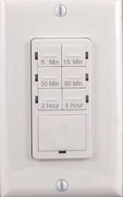
Alternative method without 3 way switches.

Install one of those in each location you want. enter image description here

Then where ever you are just push the desired time. Connect the output wires togeter at the pump.

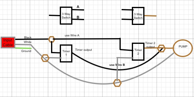
As per your request, here is full wiring for 2 timers replacing the 3 way switches.

2 timers

Disconnect the 3 way switches

1- Find the incoming power cable, using a phase tester.

2- Disconnect it from 3 way switch and connect to timer 1

3- You have to bring the Power wire to the second Timer. Use the 3 way switch wire marked A. You will find it on the second 3 way switch by using a phase tester.

4- Use the wire from 3 way switch marked B and connect to Timer 1 output.

Connect all neutrals and grounds accordingly

3
  • The alternative option with two timer switches seems most flexible. Can you please describe how to adapt the 3-way wiring?
    – Michael
    Commented Jun 6, 2022 at 14:08
  • @Michael I can do that if you provide me with picture of the 2 boxes, so I can see the wires and the colors. Also identify which one is the incoming hot, simply with phase tester and it is not switchable.
    – DIY75
    Commented Jun 6, 2022 at 20:04
  • Your diagram makes sense as is. No need to revise it with different colors. Many thanks!
    – Michael
    Commented Jun 6, 2022 at 22:36

Your Answer

By clicking “Post Your Answer”, you agree to our terms of service and acknowledge you have read our privacy policy.

Not the answer you're looking for? Browse other questions tagged or ask your own question.