2

I was reading this article, amps per leg on 220V? , and it was very helpful in understanding how to measure a 220v circuit.

My question, based on the answers given there, is how to measure the amperage of the entire panel. The measuring should be similar to measuring a 220v circuit in that measuring only one leg will give you the 220v flow for the entire house, but that would not be showing the 110v flow. So, to properly measure the current usage of my house, would this "formula" work? Using three clamp meters, measure each leg in the panel then:

--Add both hot legs together.
--Subtract the neutral leg.
--Divide by 2.
--- This would be the 220v current usage.
-- The neutral current would be the 110v current usage.
--- Add the two above together to get total current usage.
- Use those two numbers referenced to their voltage to get the wattage.

That would give the 220v and 110v current usage of the house and, referencing each to the proper voltage, determine the wattage?

1
  • 1
    That's not quite how it works. Not nearly all the 120v (not 110), usage is carried by the neutral. Circuit breakers for 120v circuits are on one hot leg or the other. These are opposite phases. In a perfectly balanced setup (not possible, but this is just an example), if 120v circuits on opposite legs drew exactly the same amount of amperage, there would be zero current on the neutral. Just measure the hots. Commented May 31, 2021 at 22:08

3 Answers 3

6

Sorry. No

You cannot tell the difference between a 10 amp 240 volt load and two 10 amp 120 volt loads, one on each leg. In both cases, you will see 10 amps on each hot and 0 amps on neutral.

In fact, if your loads on both legs were equal and constant, you could disconnect the neutral from the POCO to the panel and you’d see no difference. On the other hand, if the legs are unequal, you need the neutral to carry the difference between the two.

Bottom line, by examining only the feed to the panel, you cannot tell 120 volt loads from 240 volt loads unless the 120 volt loads are completely unbalanced.

0
5

No, that math is all goofy and will give you a lesser value than you want

If you want a single ampacity figure (presumably for peak rate setting, equipment sizing, or fusing purposes):

  • Measure the amps on hot L1
  • Measure the amps on hot L2
  • Choose the larger figure.

E.G. if the figures are 30 and 50, with neutral at 20, the answer is "50 amps". Or 12,000 VA in most of North America (240V territory).

That is what the breaker must tolerate, the generator must be rated for, and the battery inverter must deliver, and will be the basis for your peak-based electric rates in some cases.

If you want to know your actual electricity being consumed:

  • Measure the amps on hot L1
  • Measure the amps on hot L2
  • Average the two figures
  • Multiply by voltage between L1 and L2 (e.g. 240V in actual North American voltages)

E.G. if the figures are 30 and 50, with neutral at 20, the answer is "40 amps" giving 9600 watts.

That is what is being sucked out of your batteries, and (in most territories) what the "per KWH" part of your electric bill will be based on.


If you happened to notice that we don't use neutral (and don't even need to bother putting a CT on it), that is correct. The ampacity of neutral can always be inferred from the L1 and L2 current (unless you have a ground fault).

Neutral value will always be the absolute value of L1 minus L2.

5
  • 2
    For actual electricity consumed your heuristic is an approximation, of course. A more accurate method is to measure amps on L1 and the voltage of L1 (vs N), then to multiply them together and add to the same on L2. Better still requires measuring the phase shift between the line voltage and current to calculate VA/VAR and the power factor.
    – J...
    Commented Jun 1, 2021 at 11:42
  • @J... A good smart meter will give you all of that (and more). Unfortunately, most utility-installed smart meters don't provide any direct customer access beyond (at most) a pulse kWh output. Some provide a summary via customer-accessible web page, but generally very limited (e.g., a single daily value, not 15-minute values). Commented Jun 1, 2021 at 15:11
  • @manassehkatz-Moving2Codidact Yes, lots of things will give you that info. OP is asking about how to DIY it, however.
    – J...
    Commented Jun 1, 2021 at 16:08
  • @J... Sure, but that only matters if you have a lost neutral. If so, you have bigger problems... Commented Jun 1, 2021 at 19:33
  • @Harper-ReinstateMonica No, the line voltage changes day by day so you need to measure it for accurate power calculations. Using the nominal 240V is an approximation. In three-phase installations you definitely have to consider the L-N voltage (or the L-L) of each leg separately. With a split-phase transformer the two legs should be pretty close so using the LL/2 voltage is probably close enough. Nothing to do with a lost neutral.
    – J...
    Commented Jun 1, 2021 at 22:08
0

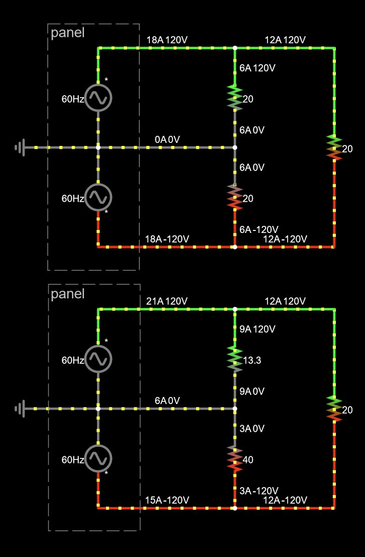
Here are some diagrams which might be helpful – snapshots of a circuit simulation.

Both circuits have identical total power consumed, just different 120V loads.

circuit diagrams

Trying to wrap my head around Harper's method of finding power usage: multiply average leg current by 240V – 240 * (L1+L2)/2. Mathematically, it's equivalent to 120V * sum of legs: 120 * (L1 + L2), so hmm.

1
  • I suppose it's only mathematically equivalent but not semantically equivalent, as the two legs start off from a single 240V phase, so the voltage of each leg may vary slightly but they always sum up to 240? (Not all too familiar with split-phase but in our three-phase land the individual voltages do swing around a bit depending on load.)
    – user1686
    Commented Dec 4, 2023 at 5:28

Your Answer

By clicking “Post Your Answer”, you agree to our terms of service and acknowledge you have read our privacy policy.

Not the answer you're looking for? Browse other questions tagged or ask your own question.