6

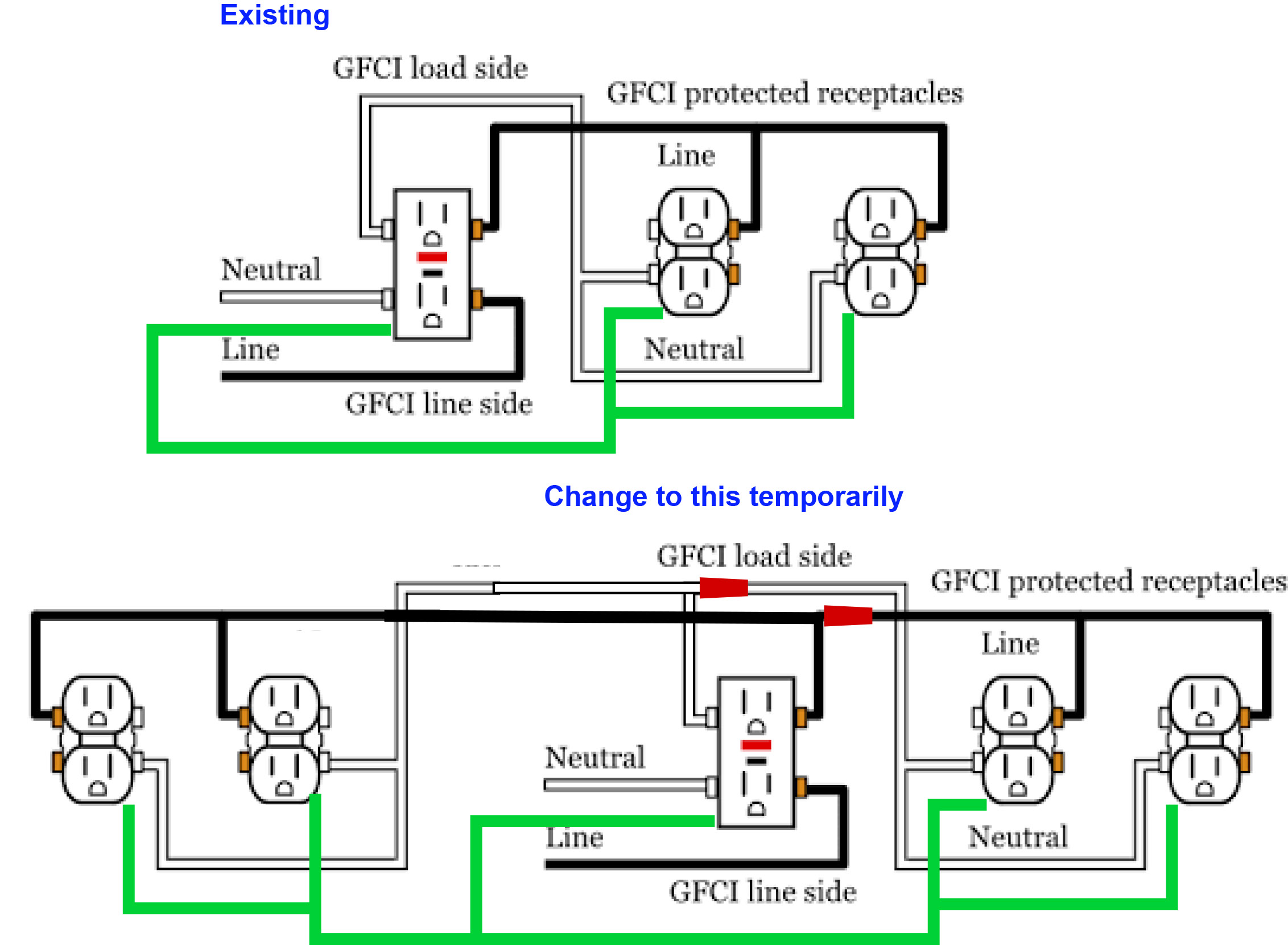
Currently, I have a GFCI outlet that has two more outlets down the line as shown in this diagram.

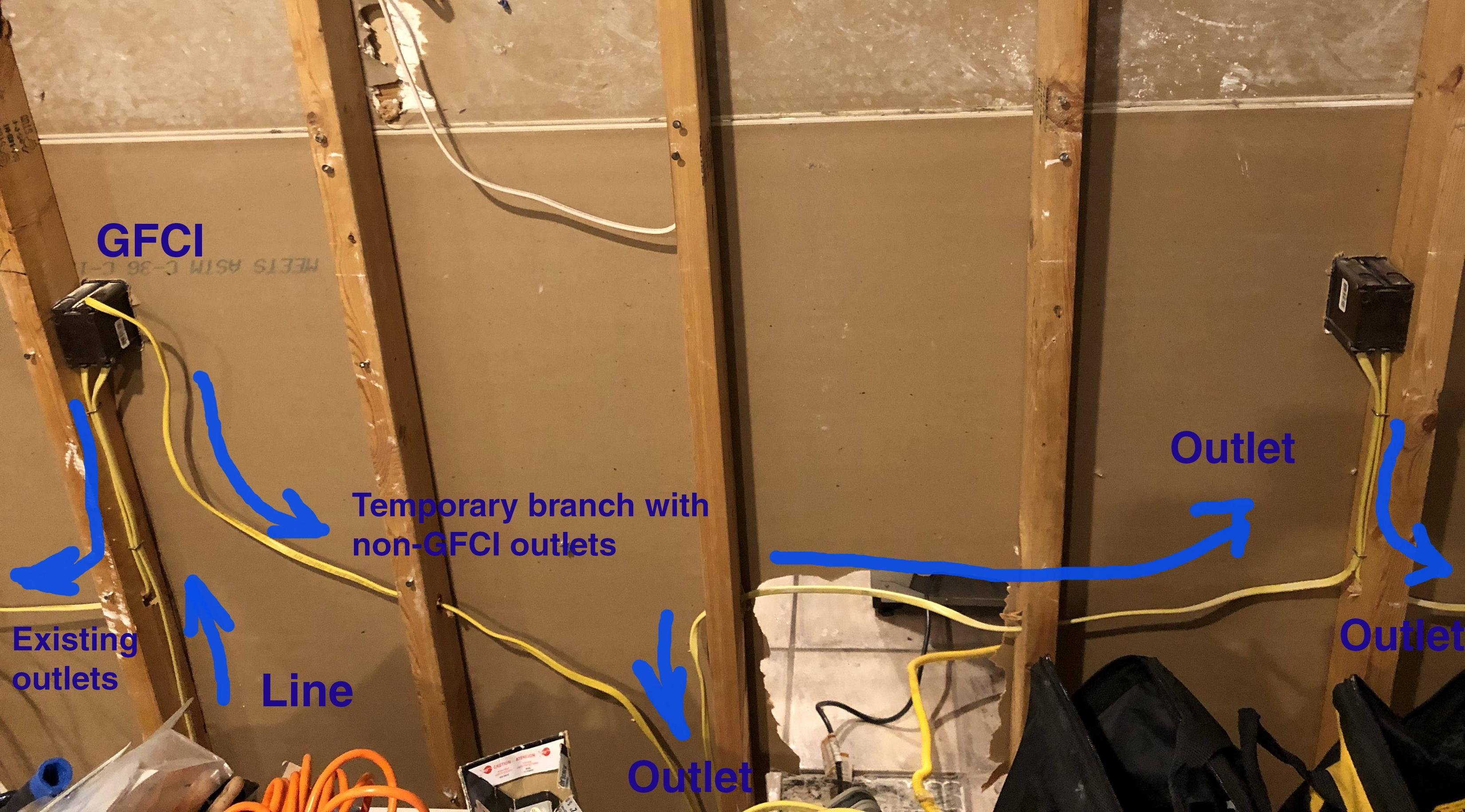
I am moving around some circuits and I need to temporarily hook up 3 additional outlets that are losing a line.

Is it proper to wire that additional group of 3 (non GFCI) outlets from the GFCI itself just like the original branch of two? I am showing that new branch with arrows. The circuit is 20A and I am not worried about overloading/tripping -it is temporary so that we have functioning outlets while the work is being done. I do have additional GFCI outlets if I need to add one in this situation. Thanks.

Thanks.

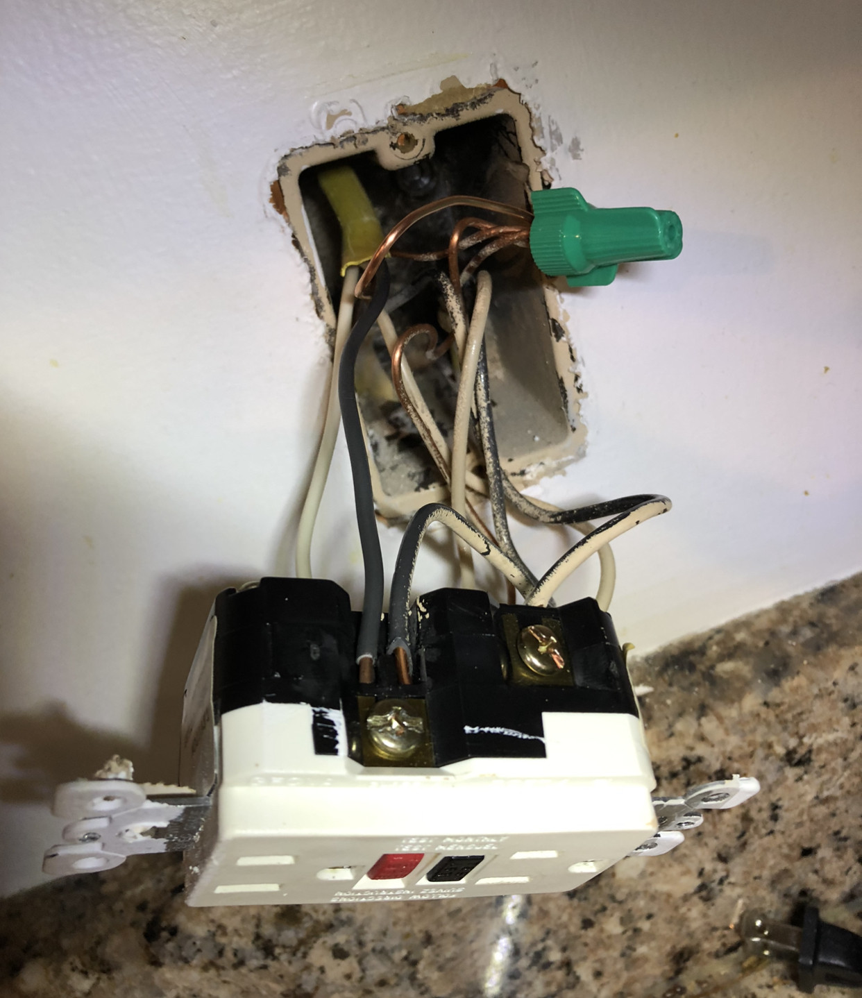
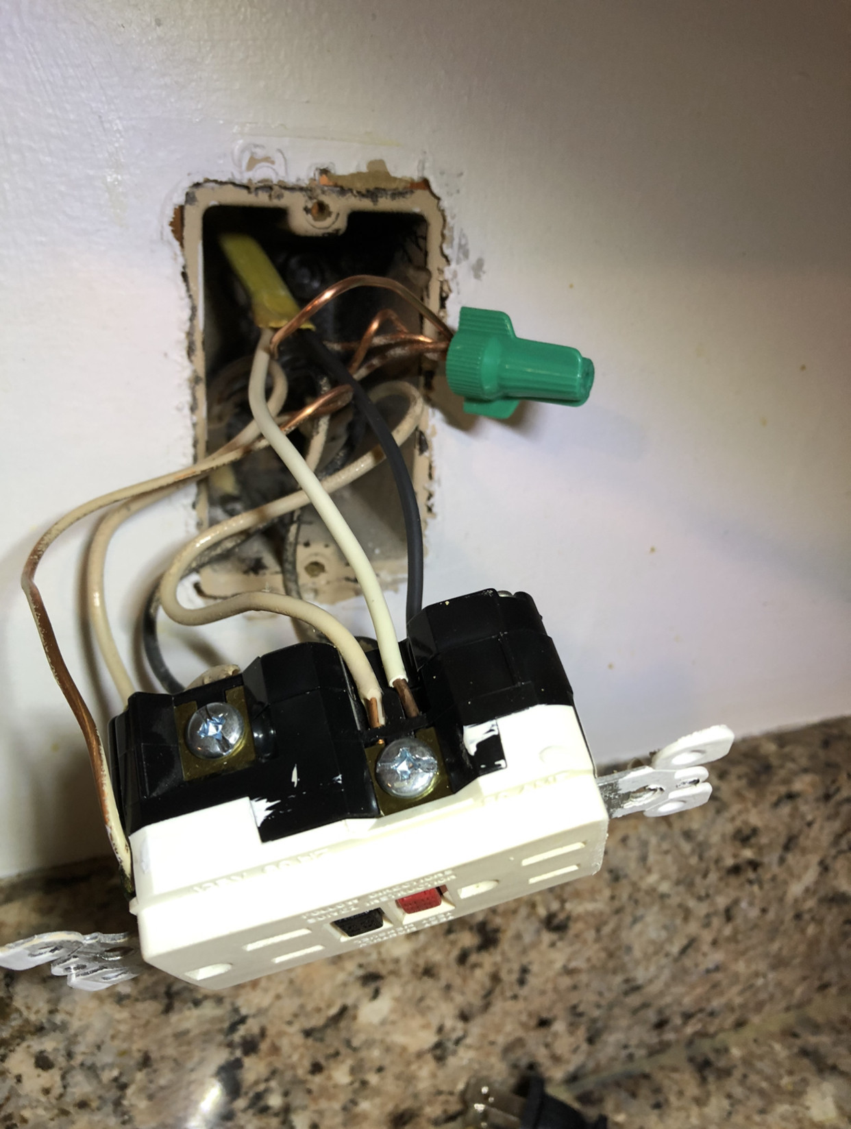
EDIT: apologies for the bad initial diagram that I pulled off off the internet in a hurry on my phone. Here are the actual photos. The GFCI has the line going into it. From there, I have a circuit branching out with two standard outlets. What I want to do is to hook up the second "branch" with 3 more outlets on the other side of the wall (temporarily, so that we have functioning outlets before the wall goes away) This branch will also be hooked up on the GFCI side (see on the bottom 2 photos how I connected them on GFCI load side. Does this look good?

enter image description here

enter image description here

enter image description here

enter image description here

6
  • What area/room do the existing GFCI outlets serve, and what area/room do the outlets you're moving over serve? Commented Sep 14, 2020 at 3:09
  • @threePhaseEel So there are two GFCI circuits each having 2 and 3 regular outlets down the line. They are both in the kitchen. The ones that need to be functioning temporarily are on a wall that is going away. The circuit feeding those outlets is going to kitchen island, where they will be GFCI-ed. The GFCI circuit that is staying is on the section of the wall that isn’t going down, but I’d love to feed off of it for the orphaned outlets in that to be demoed wall.
    – David
    Commented Sep 14, 2020 at 3:13
  • @jack. Yes, the GFCI is on the load side. It already has non-GFCI outlet on the right side. I just need to add a couple of regular outlets on the left side but I can only wire from the load side (where GFCI is connected).
    – David
    Commented Sep 14, 2020 at 3:17
  • 1
    @jack, please see the edit. I apologize for the bad diagram initially - I only had access to my phone.
    – David
    Commented Sep 14, 2020 at 3:52
  • 1
    @ThreePhaseEel please see the edit. I apologize for the bad diagram initially - I only had access to my phone.
    – David
    Commented Sep 14, 2020 at 3:52

2 Answers 2

9

Yeah, that works.

Sorry for such a short answer; your design is correct.

7
  • Awesome, thanks! Short answer is great by me ;)
    – David
    Commented Sep 14, 2020 at 5:39
  • Grey and purple for GFCI load, black and white for line, green for ground, red for switched and yellow for travelers. You got a rainbow.... stay safe out there +1
    – JACK
    Commented Sep 14, 2020 at 12:07
  • 1
    @J... The GFCI in the photo is made for that, though... most GFCIs support 2 back connections under the screws like that... there's a clamp underneath the screw. Commented Sep 14, 2020 at 15:58
  • 1
    @J... The UL approved instructions say it's Code. But you're right about neutral, sometimes you need to pigtail that even if the recep allows 2 wires... classic example is a multi-wire branch circuit where it's absolutely necessary. I don't know if Canada requires that for ALL outlets, but it's a good practice, and they often require those. . Commented Sep 14, 2020 at 17:19
  • 1
    @Harper-ReinstateMonica Yes, afaik we require it for all outlets. The idea being that you should be able to remove a device without breaking neutral continuity. For the GFCI it's questionable, I agree, though, since it's really a separate neutral bus at that point and the buck stops on the load side terminals no matter what.
    – J...
    Commented Sep 14, 2020 at 17:59
4

In your diagram the GFCI outlet is connected directly to the power source.

The additional two outlets are also connected directly to the power source.

Those two additional outlets are NOT being protected by that GFCI outlet being shown in the picture.

2
  • 1
    Ok, so I realize the diagram is wrong. I pulled it off of internet on my phone so had minimal markup tools. I will post an updated diagram in a minute.
    – David
    Commented Sep 14, 2020 at 3:19
  • 2
    please see the edit. I apologize for the bad diagram initially - I only had access to my phone.
    – David
    Commented Sep 14, 2020 at 3:52

Your Answer

By clicking “Post Your Answer”, you agree to our terms of service and acknowledge you have read our privacy policy.

Not the answer you're looking for? Browse other questions tagged or ask your own question.