1

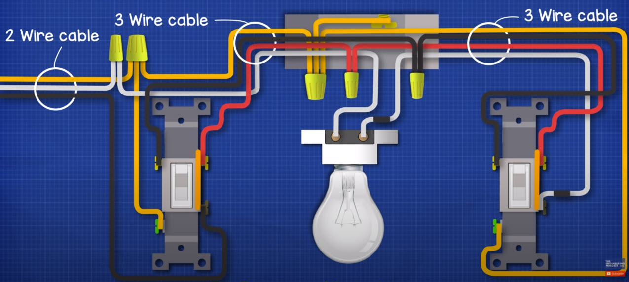
I have wired a new circuit in my house that is an outlet controlled by 2 3-way switches. I intend to plug a chain of 4 LED shop lights into the outlet. I have run 14/2 from the panel to the first 3-way switch, then 14/3 from the 1st switch to the outlet, and then 14/3 from the outlet to the second switch.

The white (neutral) wire in my 14/2 run coming from the panel connects to the white (neutral) wire of the 14/3 wire running from the 1st switch to the outlet and then connects to the silver colored terminal of the outlet. The load wire coming from the panel connects to the black colored terminal (load) of the first 3-way switch.

The red and black wires of the 14/3 wire connect to the 2 travelers of the first 3-way switch and are then connected to the red and black wires in the outlet box that are coming from the second 3-way switch. The white (load) wire coming into the outlet box from the second 3-way switch is connected to the brass colored screw of the outlet. I have put a black piece of electrical tape around the white (load) wire coming from the second switch to be able to discern it from the white (neutral) coming in from the panel.

All grounds are connected...I have double and triple checked this using a ohmmeter.

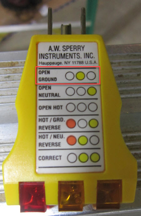
No matter what I do, when I plug in one of the 3-light testers into the outlet...it shows an open ground. If I turn one of the switches to on, it shows that the outlet has power and is correctly wired but as soon as I turn the switch off...it shows an open ground again. I have tried two different testers with the same result.

Below is a diagram of what I explained above with the exception that the light is an outlet.

enter image description here

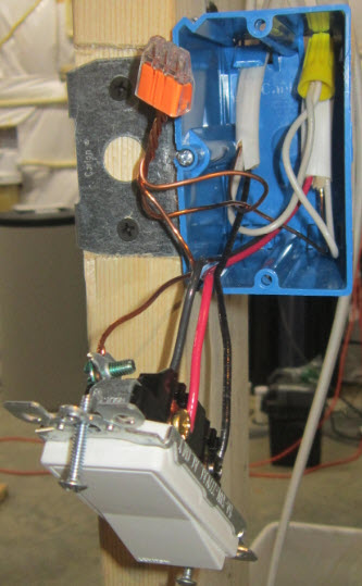
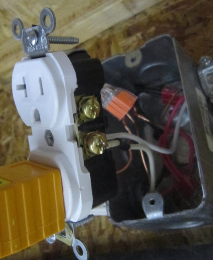
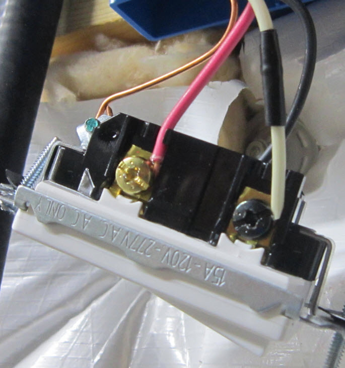
EDIT: Adding addition pictures and info. Pictures below show both switches, the outlet and the tester being used. Additionally, what I have discovered is that even though the tester is saying "Open Ground" based on the light pattern...with the switch off and no tester in the outlet I am measuring 110V AC in either receptacle. If I plug the tester into one of the receptacles (again with the switch off) I measure roughly 82V AC.

enter image description here

enter image description here

enter image description here

enter image description here

8
  • 1
    A photo of the "outlet" and the switches would be helpful. Commented Jun 22, 2021 at 3:22
  • 1
    Can you post a photo of the inside of the receptacle box please? Commented Jun 22, 2021 at 3:44
  • Are you absolutely sure it is indicating "open ground" and not "open neutral"?
    – DoxyLover
    Commented Jun 22, 2021 at 7:01
  • Added additional photos and more info Commented Jun 22, 2021 at 12:20
  • 1
    The 15A vs. 20A issue has absolutely nothing to do with the current problems. It is a code-compliance/potential safety concern. In theory, if you plugged in a heavy load (e.g., 16A continuous - like a 20A-circuit-rated heater) then you could overload the switches without tripping the breaker. Commented Jun 22, 2021 at 13:48

4 Answers 4

5

Whoops! White wire misuse

As usual, random diagrams found on the Internet are wrong.

You can't use white as a switched-hot. NEC 200.7(C)(2). White has the following priorities:

  • If neutral is present in the cable, it must be white.
  • If white is still available* and always-hot is being carried, it must be white, and marked.
  • if white is still available, then it must be used NOT for a switched-hot, and marked.
  • White can never, ever, ever be a switched-hot.

So you will need to re-jigger the wires on the switch spur to use white for one of the travelers. I recommend red for switched-hot, as that is a common color convention.

If it was me, I'd also use yellow tape to mark all travelers. 3-ways get a lot easier to understand when they look like this:

enter image description here

Grounding problems at the metal box

Also, in the metal receptacle box, you must ground the box first! Get a short #10-32 screw in the pre-existing hole tapped in the box for that (it's on the bump/dimple in upper right). When you have a surface mount steel box like that, you don't need to ground the receptacle - it will pick up ground off the box, via the direct metal-metal contact between receptacle yoke and box screw ear. (remove any of those plastic squares used to capture screws).

Switches can also pick up ground via their screw heads, even if their yokes aren't making hard flush metal-metal contact. Because they are switches :)

By the way, sorry for burying the lede, I think the grounding problem is due to the wires not going far enough into that hokey stab splicer, because the wires were previously bent. Try using a wire nut. Or the supply ground on the box ground screw, the switch spur ground on a ground clip.


* think: 12/2/2 cable which has two whites.

4
  • @harper-reinstate-monica, thanks for the detailed explanation. I implemented your suggestions and still have the same result. Starting to think one or both of my switches are bad. Not sure if they are made the same but I have another 3-way circtui put in by my builder that uses Eaton switches. I made a voltage map based on switch position and the results differed from what I am seeing with my Leviton switches. Commented Jun 22, 2021 at 22:08
  • 1
    @phy well you know, what matters is the colors of the screws, not their physical position on the device. Every manufacturer puts common in a different place, even among their own models! Commented Jun 22, 2021 at 23:52
  • @harper-reinstate-monica I have check this like 50 times...I am using red & black for travelers. The red traveler is connected to the same silver screw on each switch and same for black. The voltage just does not read right when compared to the voltage I am reading on the circuit I have using the Eaton switches. Commented Jun 23, 2021 at 0:20
  • Isn't the common labeled "common"? Commented Apr 10, 2023 at 14:25
0

I cannot read your "frizzy thing". Each three way switch has an identified terminal, typically black but it is different then the other two. On one end place the hot on the black terminal the red and black on the other two. The red and black go to the other three way switch. Place the neutral on the white wire at the switch that feeds the circuit. The two white wires connect as you show. The black terminal on the other switch connects to the white switch.

0

A 3 light tester isn't magic. It just has lights across each pair of pins. Voltage =light. No voltage =no light. Open ground can mean ground not connected. But it can also mean no voltage between ground and hot. But in this case the problem isn't, open ground. The real problem is that you should not see any lights at all when the switches are off, but you do.

Double check everything. Somewhere you have a wire connected incorrectly, either resulting in neutral switched instead of hot or some other unsafe situation.

If you can't figure it out, upload pictures of all the wires gong to the switches and the receptacle.

4
  • I think you are correct but still unable to determine what is incorrect. Added more pictures and info to the original post. Still seeing voltage (reduced) when the switch is off. Commented Jun 22, 2021 at 12:23
  • How are you measuring the voltage? Commented Jun 22, 2021 at 13:49
  • With a Fluke multimeter Commented Jun 22, 2021 at 15:07
  • 1
    How much voltage? 10V or so, unloaded, could just be induced voltage with no power behind it that will vanish if connected to any real load.
    – keshlam
    Commented Apr 10, 2023 at 14:18
0

If your ohmmeter showed ground continuity between the first switch and the outlet/light, it sounds like the problem is upstream (potentially at the panel).

First ensure that your voltmeter reads 120VAC between the hot and neutral wires on the 14/2 coming from the panel. Then check the voltage from neutral to ground. If this is not 0 volts (or within a small margin of error), the connection at your panel is loose or incorrect.

3
  • 1
    While this is likely correct, answers to very old questions such as this one should be unique enough to add something missing from the Answers already given. The advice in your post has already been given in the top-rated answer to this question. You can take the tour to find out more about meaningful contribution here. Commented Apr 10, 2023 at 20:11
  • Your answer could be improved with additional supporting information. Please edit to add further details, such as citations or documentation, so that others can confirm that your answer is correct. You can find more information on how to write good answers in the help center.
    – Community Bot
    Commented Apr 10, 2023 at 20:34
  • I did not see any other answer mention checking connections at the panel, including the top answer. Perhaps I have misread what was written, but I do not see similar advice given by anyone else here.
    – mwaterbu
    Commented Apr 20, 2023 at 1:34

Your Answer

By clicking “Post Your Answer”, you agree to our terms of service and acknowledge you have read our privacy policy.

Not the answer you're looking for? Browse other questions tagged or ask your own question.