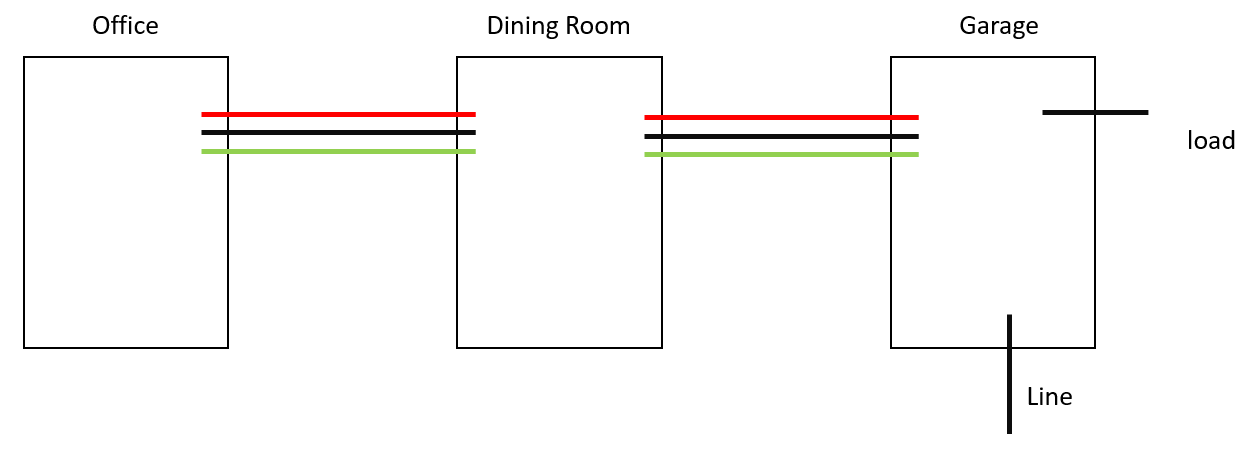
Yes, it's possible to rearrange things to fit what you want
The trick to this is that while Lutron's diagram shows line and load on opposite ends of the circuit, nothing stops you from wrapping that load wire back around to the first box then connecting to the existing load wire there. So, given that you have /3 going down the spur and starting with the master dimmer at the garage:
- The garage dimmer ground connects to any existing grounding wires
- Line-in at the garage goes to black on the garage dimmer
- White (taped black) on the spur cable (going down to the dining room + office) goes to blue on the garage dimmer
- Black on the spur cable goes to brass on the garage dimmer
- Red on the spur cable gets connected to the load wire
- And the white wires from the line and load cables connect to each other, but not to the taped/flagged white wire in the spur cable
Moving onto fitting a remote at the four-way location (dining room) now:
- The remote's ground gets connected to the existing grounding wires, as one'd expect
- The two red wires get nutted together
- The two black-taped white wires get nutted together and to a pigtail to the blue screw on the remote
- The black wire from the garage side of the four-way goes to the black screw on the remote
- And the black wire from the office side of the four-way goes to the brass screw on the remote
Finally, fitting the remote at the office is simple:
- The ground wire on the remote here gets connected as-expected
- The red wire goes to the brass screw
- The taped/flagged white wire goes to the blue screw
- And the black wire goes to the black screw


