0

This is my first post here so I won't take offense in any restructuring, closing, migrating...


  1. Project description

I have a tank of water, and its level is always decreasing (for all intents and purposes, it's like it's leaking). I have a pump constantly adding water into this tank. I want to make sure the tank never overflows (I can't tell in advance how fast water will leak, and pump rate is constant).

  1. Materials

So I have a Eltako MFZ61DX-UC delay relay and a float switch (tiny plastic floater that closes the circuit based on water level). What I want to do is quite simple: when water gets too high, stop the pump for 30 seconds so that water level lowers.

The float switch can be placed in either direction, meaning it's either always open, and closes when water gets too high, or it's always closed and opens when water gets too high. That's easy. But it's also important to delay so that the pump doesn't just keep turning off and back on again when water level is close to the float switches level.

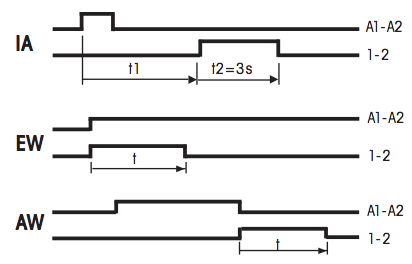
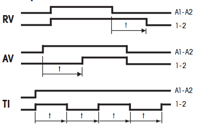
That's where the relay comes in. It has several delay functions to choose from (and more info can be found on its notice):

relays options 1-3 relays options 4-6

  1. Question

Based on this 1 page notice for the relay, is this doable? Looking at the 6 modes of this relay, it looks like all you can do is temporarily turn on something, not temporarily turn it off. Am I misunderstanding this? Is there some way to wire it so that it'd work?

I have never used a relay but I feel like logically, it should switch between 2 circuits (and not just open and close one), but if that's the case, this notice doesn't make a good job telling me how to wire this whole thing.

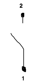
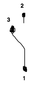
If I can oversimplify my question with 2 simple drawings: the notice indicates two terminals for the relay (1 & 2 on the drawing on the left), but I'd like to know where is the third one (3 on the drawing on the right).

described circuit desired circuit

  1. Bonus question

In case the first question doesn't work out, can someone point me towards a relay that can actually do what I want here?

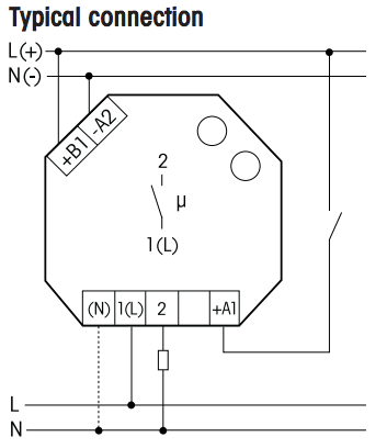
For the lazy amongst you, here's a "typical wiring" of this relay, found on the notice. With that and everything else provided before, you should have enough info to answer my question without looking through the notice.

enter image description here

2
  • What if the water level doesn't lower during those 30 seconds? Do you want to try to restart the pump, or lock it out until the water lowers? Commented May 28, 2016 at 4:10
  • @ThreePhaseEel Good point. I'd like to absolutely wait. It's more important that water doesn't overflow.
    – Sheraff
    Commented May 28, 2016 at 8:42

2 Answers 2

2

You are correct that a dead-band is needed to prevent the pump from constantly cycling on and off when it is near the set point. That is why these systems use a high and low float or sensor.

It seems like you are making this way too difficult by timing the pump off instead of using a second float.

A fill pump controller like this would do what you want.

Most tank level control systems use something like this, not a timed system.

Good luck!

3
  • It's true that I'm going off an idea here and maybe having 2 sensors instead of just the one would make it easier. But I don't want to activate the pump when water gets low, I want to stop it when it gets high, which is something harder to find in off-the-shelf solutions. Additionally, I already have a delay relay at home so I thought I'd try and use it. I know for certain that just stopping the pump for 30s when water gets too high would do the trick for me, and then, I don't really need 2 sensors.
    – Sheraff
    Commented May 28, 2016 at 10:47
  • @Sheraff - Get the dual switch float sensor or its equivalent. The timing relay is not the appropriate component for your water tank.
    – Michael Karas
    Commented May 28, 2016 at 23:10
  • @MichaelKaras, I get that this might not be the proper way to do it, but I don't understand why it wouldn't work.
    – Sheraff
    Commented May 28, 2016 at 23:26
2

As a general rule, Archon is correct -- it's better to implement a deadband as two sensors (one for the high setpoint and the other for the low setpoint) rather than relying on a timer to avoid short cycling and other such erratic behavior.

If you cannot obtain dedicated fill pump controllers, but a NO and a NC float switch are available, a crude fill pump controller can be constructed from a suitably rated dual pole relay. Simply connect the relay coil in series with both float switches (the NO is the lower limit, while the NC is the upper limit), one (NO) relay contact in series with the pump, and the other (also NO) relay contact across the lower float switch contacts. This arrangement causes the relay to "stick" itself up when the lower limit closes, and then drop out and "unstick" when the high limit opens. (Commercial controllers use similar logic, but with more sophistication to deal with dead pumps etal)

If a second float switch is absolutely unavailable and you need this working ASAP, you will need a suitably rated SPDT or SPST-NC relay or contactor. Wire the float switch as NO to your existing time relay's contact terminals and connect power to the time relay, and set it for delay-OFF (i.e. the RV function on the relay) with a 30s delay. Then connect the 1-2 contact on the time relay in series with the plain relay's coil, and the plain relay's NC contact in series with the pump. (The plain relay logically inverts the time relay's output, as your time relay only has a SPST-NO contact.)

Your Answer

By clicking “Post Your Answer”, you agree to our terms of service and acknowledge you have read our privacy policy.

Not the answer you're looking for? Browse other questions tagged or ask your own question.