5

I have a "ring main" with many sockets on it, it is clear that it has been extended over the years.

How do I trace the cabling to.

  • Check that it is a single ring
  • That only one socket is on each spars
  • That there are not any other issues.

I am hoping for a testing method that I can just apply “set by set”; assume I have access to a good quality resistance meter

Is there any software I can type all the resistance readings into that will “solve” the system and will then tell me:

  • What additional readings it needs
  • Or how all the sockets are connected.

Related but a much easier problem: Are there any “easy” ways to trace a home electrical system?


Update:

The issue I have with the standard test method and all current answers is that they assume that the sockets are connect in a single ring – I don’t know how they could detect for example two rings that have their ends joined just before the consumer unit. Or a spars that is connect to anther spars rather then directly connected to the ring.

The test in the wiring standard is very good at finding common errors like a wire that is not connected, or a live that is connected to a neutral; however the test seems to assume that the wiring is basically a valid single ring to start with. This is not a valid assumption on an old system you don’t know the history off!

2
  • Are you willing to disconnect wires to do this, or are you looking for a non-intrusive solution?
    – gregmac
    Commented Mar 19, 2011 at 22:56
  • I am willing to disconect some wires, but don't wish to disconnect all sockets
    – Walker
    Commented Mar 20, 2011 at 22:34

3 Answers 3

2

i don't know if this is the right way, but here's what i came up with.

THIS HAS THE POTENTIAL TO BE AN EXTREMELY DANGEROUS PROCEDURE. DO NOT ATTEMPT UNLESS YOU HAVE THE PROPER TRAINING TO UNDERSTAND WHAT IS BEING DESCRIBED HERE.

what i'm going to suggest is that you bridge the hot and neutral on one outlet in the ring. then. obviously, before you even think about attempting anything like this, you must turn off and disconnect the hot and neutral from the consumer unit. disconnecting the hot and neutral from BOTH sides of the ring is very important to the accuracy of your readings.

once you have bridged an outlet, you can take resistance readings between hot and neutral. if you have one outlet that you can be fairly certain is the first or last outlet on the ring, you can use that as your bridged outlet, then figuring out the order of the ring is as simple as sorting the list by resistance.

here's an example:

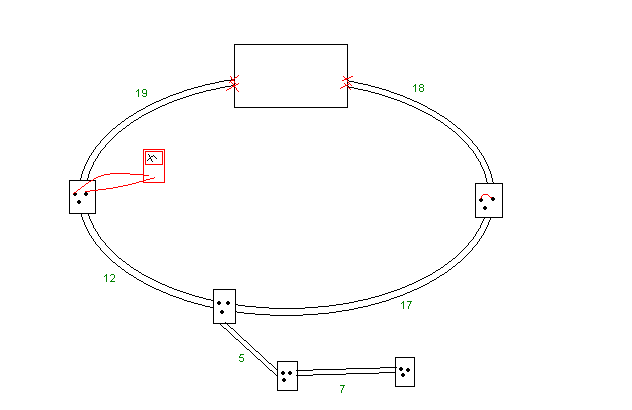
enter image description here

the black lines are wires. the red X's mark where the wires should be disconnected. notice the outlet on the right is bridged and a multimeter is connected to the outlet on the left. the green numbers are the resistances of the wires. obviously the numbers are not realistic, but this is just an example.

in the picture, the multimeter would be reading 58: 12 + 17 + 17 + 12 (that's the wires to outlet on the right and back).

the outlet on the bottom of the ring would read 34: 17 + 17.

since none of the outlets on the spar are bridged, they will not affect the reading above.

if you can't identify the outlets at the end of the ring, you can connect the hot/neutral on one side of the ring at the breaker, then measure the resistance of each outlet. the one with the lowest resistance is the outlet closest to that end of the ring.

the tricky part is identifying spars using this method. it might be obvious based on the resistance readings, but it might not be.

6
  • you are assuming it is a single ring, also even valid spars would give invalid results with your method.
    – Walker
    Commented Mar 22, 2011 at 19:14
  • untrue. it would be difficult to identify spars properly, but a spar would not interfere with correctly ordering the outlets on a ring.
    – longneck
    Commented Mar 23, 2011 at 3:03
  • 1
    @longneck, but it is not save to have spars connect to spars due to overloading the cables
    – Walker
    Commented Mar 23, 2011 at 9:36
  • ok, sure, it's not safe. but what does that have to do with your question? you asked about mapping out your outlets to figure out how they are wired. that's what my instructions are for. once you have the map, you can pull off spar outlets and look at the gauge of the wire.
    – longneck
    Commented Mar 23, 2011 at 14:24
  • 1
    @longneck, but how do I tell the difference between a spar taht has a spar comming of it, and a socket on the ring?
    – Walker
    Commented Mar 24, 2011 at 9:24
1

if you can get your hands on a TDR (time domain reflectometer) you can use it to measure the distance to the end of the ring from an outlet.

  1. turn off the power to the ring and disconnect the hot from both ends at the breaker.
  2. using the TDR, measure the length of the hot circuit from where you just disconnected it at the breaker. that is the total circumference of the ring.
  3. connect the TDR to the hot of an outlet. the TDR should return two "open" or "end of wire" values. this will tell you how far this outlet is from each end of the ring.
  4. back at the consumer unit, take a short piece of wire and temporarily attach it to one of the live wires you disconnected and measured in steps 1 and 2. then remeasure the same outlet from step 3. the new measurements will tell you which "leg" of the ring goes to which wire.
  5. repeat step 3 (and step 4 if needed) for each outlet.
4
  • you are assuming it is a single ring, also even valid spars would give invalid results with your method.
    – Walker
    Commented Mar 22, 2011 at 19:15
  • untrue. if you TDR from the end of the ring and you only get one "open" or "end of wire" distance reading, then you know it's a ring with no spars. if you get n open readings, then you have n-1 spars. from there it's just a matter of finding the outlet with the shortest reading for a possible spar. if this doesn't make sense, i'll draw a diagram for you.
    – longneck
    Commented Mar 23, 2011 at 3:01
  • is a TDR really that good with household electric wiring that has normal screwed junctions etc? (The resistance of connections will not match the wires, so will there not be some reflections from each screwed connection?) ? How good a TDR would I need for this, and can they be rented in the uk?
    – Walker
    Commented Mar 24, 2011 at 9:29
  • 1
    yes, a good TDR can tell the difference between a screw connection and the end of a wire. the kind of TDR you need would be kinda pricey to buy, but if you could rent one, then whoever you are renting it from could suggest the correct model.
    – longneck
    Commented Mar 24, 2011 at 14:16
0

To work on complex house wiring in the UK you are required to be 'competent' and my feeling from your questions is that you are not and that you need to get a qualified electrician inspect the wiring.

I bought a decent book on house wiring with good diagrams and checked many website before attempting small jobs but still know that only a qualified electrician has the complete knowledge to test house circuits properly for faults.

2
  • 1
    The issue I have is that the standard test an electrician does on a ring main, only give valid results if the ring main is wired as a single ring - all find and good if the electrician has wired the ring main, but as this is a old house all bets are off.
    – Walker
    Commented Mar 22, 2011 at 19:16
  • 2
    All the electrician I have round to quote have basic said they would only test their work and could not tell me if the current ring was valid in all ways.
    – Walker
    Commented Mar 22, 2011 at 19:27

Your Answer

By clicking “Post Your Answer”, you agree to our terms of service and acknowledge you have read our privacy policy.

Not the answer you're looking for? Browse other questions tagged or ask your own question.