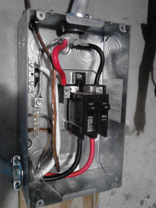
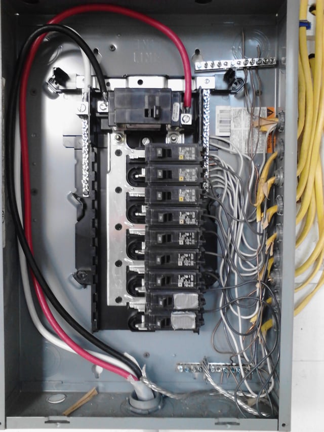
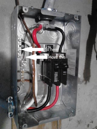
I've labeled your image, to help you understand what's going on.
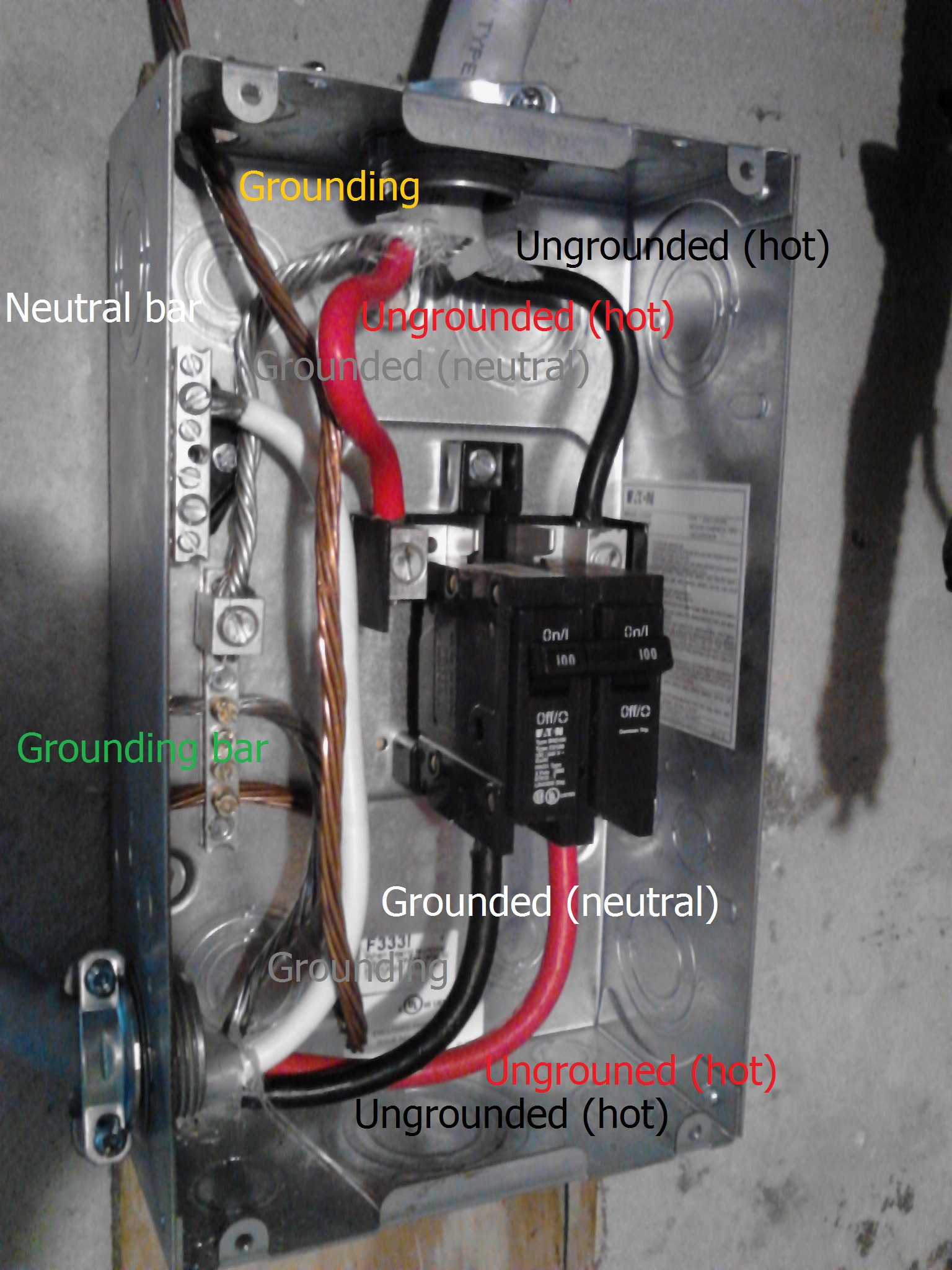
Off to the left, the grounding electrode conductor enters the box and terminates at the grounding bar. The feeder coming in the top of the disconnect has three wires, two ungrounded (hot) conductors, and a grounded (neutral) conductor. The two ungrounded (hot) conductors terminate at the disconnect, as they should. The grounded (neutral) conductor terminates at the grounding bar, as it should if this is where the service is grounded.
The feeder leaving the bottom of the panel has two ungrounded (hot) conductors, which terminate at the disconnect as expected. The grounding conductor terminates at the grounding bar, as it should. And the grounded (neutral) conductor terminates at the neutral bar. Unfortunately, since this appears to be where the service is grounded, the grounded (neutral) conductor from the lower feeder should be connected to the grounding bar.
As it's wired now, the grounded (neutral) from the lower feeder is connected to an isolated neutral bar. Which means that the grounded (neutral) conductor feeding the panel is floating, or not electrically connected to ground. Without a reference to ground, the voltage potential between either of the ungrounded (hot) conductors and the neutral can be anywhere between 0 - 240 volts.
Solution
Service grounding location
If the disconnect panel is where the service is grounded, you should move the white wire from the lower feeder to the grounding bar. Or you could bond the neutral bar to the grounding bar, using an appropriately sized conductor.
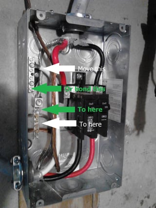
Click for larger image
Not service grounding location
If this is not where the service is grounded, you should move the bare conductor from the upper feeder to the neutral bar.
Click for larger image
Based on what you've said in comments; and because it's a 3 wire feeder and not a 4, it appears that this is where the service is grounded.
