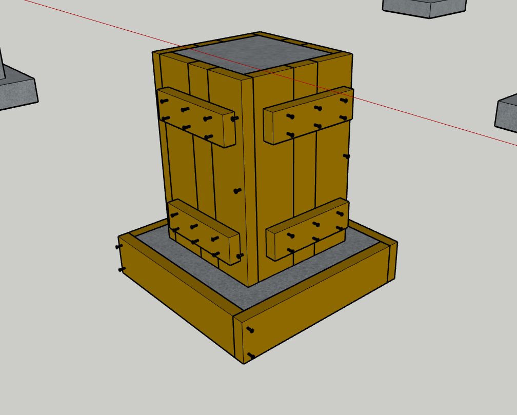
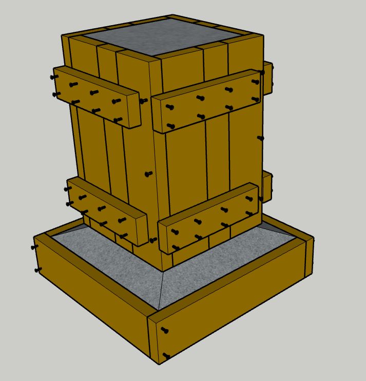
I'm designing a post and beam shed with a pier/footing foundation. I have access to an endless supply of free 2x4 and 2x6 dunnage, so I'm designing the forms with that rather than plywood. Does anybody see anything wrong with this design as far as strength and blowout? The pier is 13"x13"x2' and the footing is 22.5"x22.5"x5.5". I'd appreciate any insights or suggestions. Thanks!
-
Depends on the load applied, and on the bearing capacity of the soil, and the frost-line depth. You haven't mentioned any of those. I also don't see any indication that you'll be reenforcing your piers, which is usually a pennywise-pound-foolish choice.– EcnerwalCommented Feb 20 at 20:38
-
Appreciate the responses. Engineering has been done. The strength and proper depth of the piers are not the concern, only the pier and footing forms. Take care.– DerekCommented Feb 21 at 3:54
-
Also, I'll consider throwing a couple lengths of rebar in each one for good measure. I agree Ecnerwal, it's a cheap insurance policy. I tend to be a belt and suspeners kinda guy as well.– DerekCommented Feb 21 at 4:06
-
That's an odd design. All of that bracing all over the place, but then zero sway bracing along the front line. Are there steel tension X braces immediately under the rafters or something to transfer some of the back line's bracing strength to the front line? Or maybe those shallow arches have rigid connections to the columns?– pophamCommented Feb 21 at 19:55
-
Are these gonna be monolithic pour, or are you gonna pour the spread footing first?– HuesmannCommented Feb 22 at 14:06
3 Answers
I don't see any real problems. Deck piers in my region are almost never internally reinforced, so that doesn't concern me. Nor do your dimensions, which seem reasonable. Do make sure they're below local frost depth.
Some general suggestions:
Consider lifting the pier form 2-3 inches above the footing form top and letting the concrete slough out to the footing form, creating a sort of pyramid. With your design you have an inverted cantilever, so the inside corner at the base of the pier is a weak point. If you thicken that a bit the footing becomes a belled, integral part of the pier instead of a separate structure.
Wrap your pier form strapping fully around the form, with laps opposing those of the form itself. Screws are probably going to hold in tension just fine for that short pier, but ideally you have some screws in shear at all corners as well. You could use fewer at the interior, then.
-
1Thanks for the insights isherwood. I've edited my post to show an updated model with the pier riased 2" from the footing and the form straps overlapping the form sides. As an aside, I read Earth Abides for the first time a couple months ago, great book. Take care.– DerekCommented Feb 21 at 3:51
The footing is below grade, so shaping the top of the spread footing to shed water is foolish. Box the concrete in from above down there to avoid problems. Uplift from pressure on that cap then becomes an additional problem.
ACI 347 prescribes formwork design for concrete placement. For your short little columns, you just use hydrostatic pressure for design. 2'-5" tall implies (150psf)(2.5ft) = 375 psf pressure. Over a 22.5" width (call it 2'-0), that's a force at both ends of your bottom boards of 0.5(2ft)(5")(1ft/12")(375psf) = 160#. The NDS specifies that screws and nails into end grain have zero withdrawal strength, so that connection down there is a definite problem, especially if you'll be doing internal vibration (with a concrete vibrator submerged in the concrete).
A cap on the free surface down there should cross the joint and provide sufficient reinforcement for its top edge. For the bottom edge, I would put dirt back around the form and hand tamp it to get a layer of soil all the way to the top of that 5" edge.
Another option is to construct each footing with a cold joint at the interface between footing and pier. I assume that there's rebar already spec'ed at the interface.
Moving up to the pier's base, the 13" width combines with a 300 psf pressure to provide 0.5(13")(1ft/12")(6")(1ft/12")(300psf) = 81# at the end of each side. The center fasteners get the same load, 0.5(13")(1ft/12")(12")(1ft/12")(150psf) = 81#. 3" long #8 screws have a withdrawal strength of about 125# and a lateral strength of about 80#. For combined loading from the pressure on both sides, that's a strength of (125#)(80#)/[(1/2)(125#) + (1/2)(80#)] = 100#. The demand is [(81#)2 + (81#)2]1/2 = 115#. The #8 screws, then, are a little out of their league with only 3 fasteners. That's with Spruce-Pine-Fir lumber, though. For Douglas Fir or Southern Pine, just 3 of those fasteners is sufficient.
Isherwood's strapping is a wise detail to avoid withdrawal load on the fasteners, so duplex nails become feasible without a mess of them. Technically, duplex nails have a withdrawal strength when installed into an edge like you have detailed, but it's only something like 40# each.
And theoretically, the capped spread footing generates 700# of uplift, [(22.5")2 - (13")2](1sf/144si)(300psf), so your footings would typically be staked down (or constructed with that cold joint). To save a buck on concrete delivery, I might place just the bottom 6" or 7" at each location, vibrate, and then cycle back to the start and place the remainder, taking it easy with the vibration down low to avoid activating much of that 700#. I'd still use at least 2 stakes per form, though.
-
Thanks for the thorough reply popham, I'll tweak my designs accordingly. All wood is Doug-Fir. I plan to backfill around the footing form before the pour, but I like the idea of capping it. Also like idea of splitting each into two separate pours to decrease possible uplift issues when vibrating. Thanks again.– DerekCommented Feb 23 at 18:24
-
@Derek, Doug Fir? Nice. I too am blessed with Doug Fir. I just put things in terms of SPF around here to avoid asking a question.– pophamCommented Feb 23 at 19:24
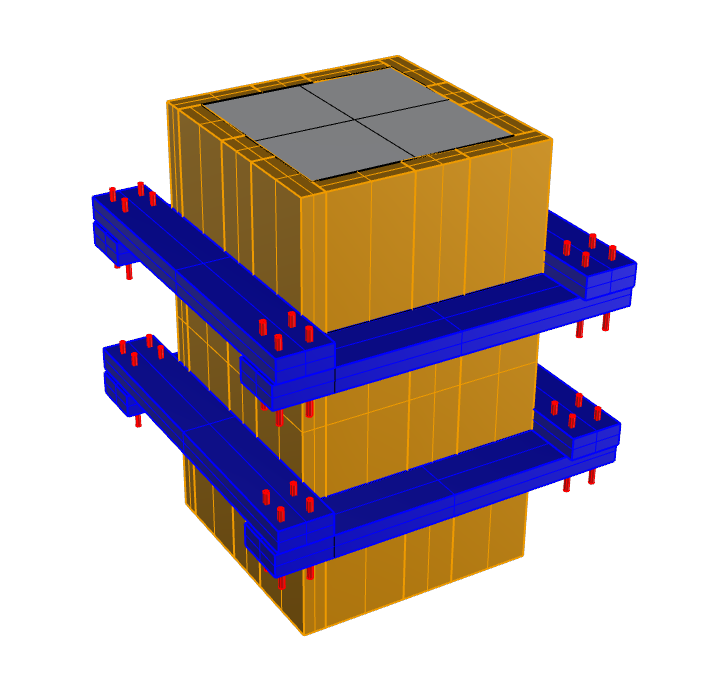
Orienting the 2x4 so that their strong axis is engaged would likely improve the stiffness of the formwork.
As drawn in the question, I would be concerned about bulging out of the formwork due to the orientation of the 2x4's.
-
Using quick, very conservative assumptions (even for SPF, although I guess this is Doug Fir), I get a 0.01" max deflection and 80% demand/capacity ratio for strength. The fabricated form systems that look like your detail tend to be designed to scale way up to much taller than 2 ft.– pophamCommented Feb 23 at 19:38
-
Thanks for the reply CrazyArm. I agree your suggestion is definitely the preferred form design for a large form and I have indeed seen this method numerous times while researching. Considering my piers are so small/short, I'm hoping to get away with just the overlapped strapping.– DerekCommented Feb 25 at 19:21


