0

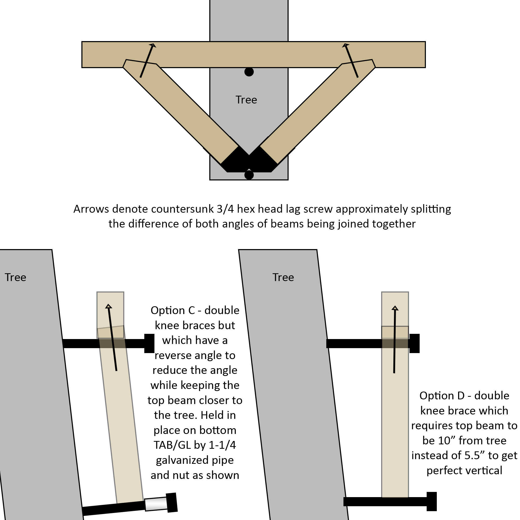
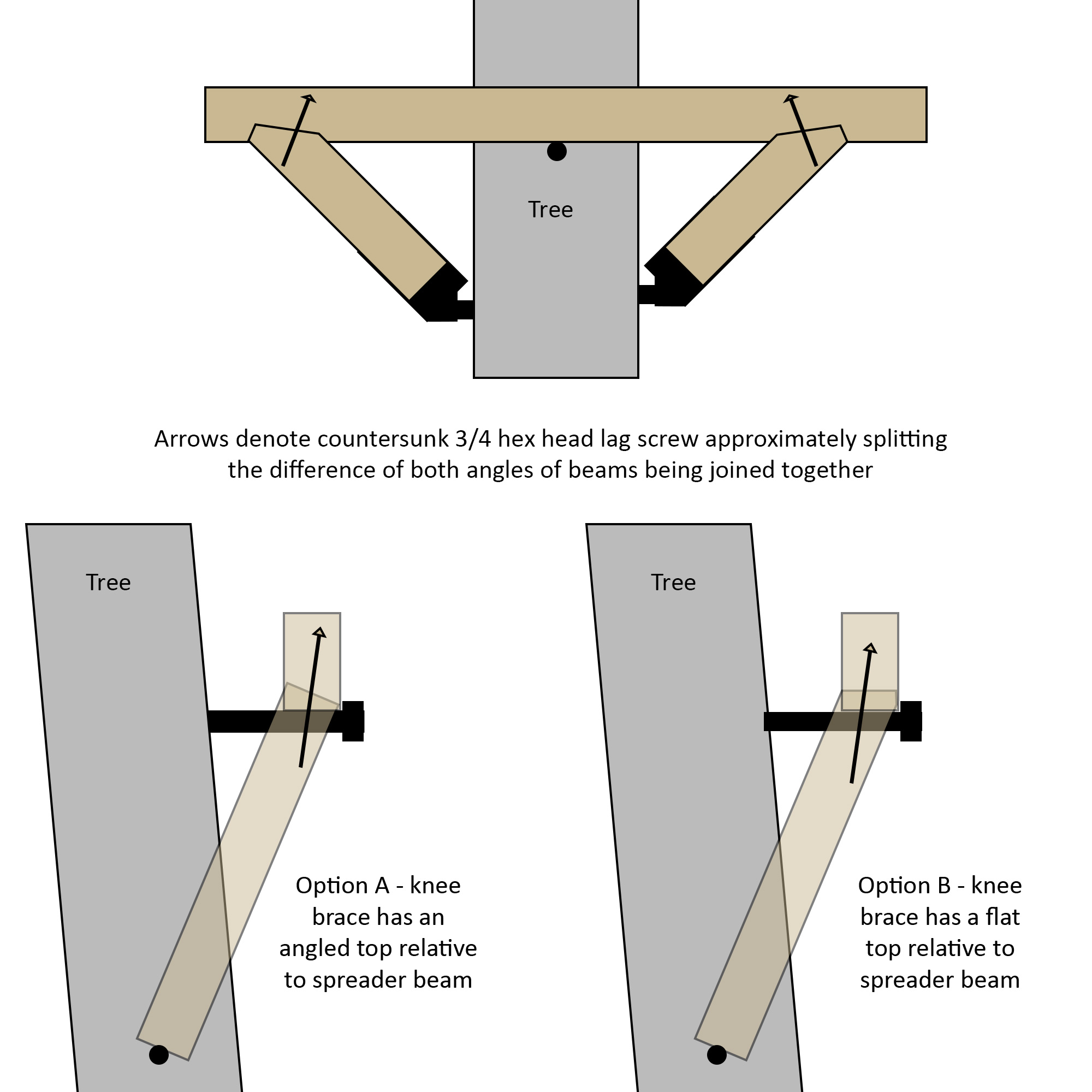
I'm trying to figure out which is the correct mating angle out of Option A and Option B seen below (or perhaps something else different altogether) to properly help support the spreader beam using knee braces. Options C and D are another possible route but I'd strongly prefer option A and B if they aren't significantly inferior since I've done some work towards that end and bought some stuff already.

A challenge arises because the knee braces must be at an angle due to the tree lean and I can't just make a simple 90+45 degree tri-beam / double knee brace. I can do it but with the drawbacks as seen in options C and D.

(NOTE: the angles of the knee brace in option A and B is really more like half as severe of an angle as it looks) enter image description here

enter image description here

2
  • In Option A & B, are the boards overlapping (as drawn), or will they be cut into mating surfaces so that the ends butt up? If they'll be butt joints, I would go with option B because that simplifies the cut for piece that goes above, and because it puts the vertical weight onto a horizontal surface instead of an angled surface that's angled away from the tree.
    – FreeMan
    Commented Oct 10, 2022 at 15:43
  • @FreeMan they will be cut into mating surfaces so the end of one fits into the slot as seen in the top front-on image in the diagram. So do you think option B is better structurally then? Thanks
    – g491
    Commented Oct 10, 2022 at 19:31

1 Answer 1

2
+100

This is a very complicated engineering question with incomplete data. You appear to have a knee brace that is attempting to support a heavy offset load, but you are attempting to control both location and shear with bolts.

This is not a good idea. Classic timber framing uses mortises and tenons which transfer the load down and through the supporting member, and keep the whole assembly from shifting in all three dimensions. A single lag screw is probably fine if this thing is wildly overbuilt, but I like option D the best followed by option B. Option A seems to create rotational force that will cause the top beam to slide off the knee brace, or at least flex the lag bolt. It could fail catastrophically. B is better, but under heavy load, the whole assembly will rotate a bit away from the tree.

C creates the problem of finding a long pipe that resists flexing under load, and won't be pulled out.

But again, not enough information to make a really informed judgement.

3
  • What do you think about option A if the angle is 11 degrees (about half as much as the drawing shows), and there are two 3/4 lag screws per knee brace joining it to the spreader beam (one is fairly long)? Trying to avoid rework if possible but want to be safe. Another variation would be to also add a stainless joiner plate on the right side of the diagram to help handle / minimize flex. Thanks
    – g491
    Commented Oct 12, 2022 at 6:16
  • Two is probably better than one (unless you split the wood). I tend to prefer carriage bolts to lag screws in this application, because over time, the flexing tends to compress the wood fibers and make the screw hole bigger. 11 degrees is better than the picture, but it depends on how accurately you can mate the surfaces -- worst case you basically just have a lag-screw acting as a pin with significant shear forces on it.
    – gbronner
    Commented Oct 12, 2022 at 13:48
  • Sorry if this is a silly question, but is there a reason why carriage bolt instead of hex bolt? Thanks
    – g491
    Commented Oct 12, 2022 at 21:17

Your Answer

By clicking “Post Your Answer”, you agree to our terms of service and acknowledge you have read our privacy policy.

Not the answer you're looking for? Browse other questions tagged or ask your own question.