0

I am working on installing a DC to AC inverter (Victron Energy Phoenix 800VA) in my little teardrop RV such that the Inverter powers ALL the AC ports when it is turned on. The objective is to have it feed the AC panel when on. The concern is getting the AC-DC battery charger to be automatically shut off when I turn on the Inverter.

The setup is pretty simple:

Today: Shore power > AC panel > AC-DC battery charger > 12v battery & 12v panel

With Inverter installed: 12v battery > DC to AC inverter > AC panel

There is no problem as long as the Inverter stays off, but once the inverter is turned on, the AC-DC charger will try to charge the battery from the Inverter. I have seen the solution is to put a contractor (AC relay) between the AC Panel and AC-DC charger that is switched by power coming from the Inverter. I totally get the concept, I have some implementation questions:

  1. What contractor should I be using? Shore power is 110v @ 30 amp, the AC-DC charger is nowhere near that power draw and the Inverter is only about 800 watts. I know the contractor needs to have an "Open" unless it is charged (by the Inverter) so that the default mode is shore power will run to the AC-DC battery charger.

  2. How do I wire it to the inverter exactly? Will both hot & neutral go through the contractor or only the hot like a relay?


I would LOVE to get one of the Victron Energy Multiplus unit's, but there are some big problems with that:

Multiplus size: I am only installing Victron Energy Phoenix 800VA, which means if I were to use the Multiplus, I would install the 800VA unit. The problem comes from the fact I am NOT expecting to run the high current items off this inverter: A/C, build it electric heater, and Microwave. I will only use those when connected to shore power. From everything I can tell about the Multiplus 800VA is that when connected to shore power it won't allow more than the 650Watts through to the panel, preventing me from ever using the high current items.

There are reasons I am NOT looking at a larger Multiplus: From everything I understand about the larger Multiplus units, I would have to hook up a big battery bank, somewhere between 300~500Ah. The teardrop does not hav=e the space and I do not want to spend the money on batteries I don't NEED.

All in all, it seems the best solution is a custom system that allows the full 30 amps when connected to shore power to get to the panel but correctly switching it when offshore power to allow the Victron Energy Phoenix 800VA to power the panel without feedback.

1
  • it's so simple, it's actually quite complicated, given the AC and backfeeding in play here. I would replace the switch that turns the inverter on with a DPDT and use the other half to disconnect the charger when the inverter is activated.
    – dandavis
    Commented Aug 25, 2021 at 22:55

4 Answers 4

3

There's an easier and more passive way to do that thing. And it won't have any vampire draw on the battery.

Note that as an RV, you must comply with your territory's electrical code, such as NEC in the US and central America. This is AC power. There's no "wing-dinging" this together with non-listed components from Mouser or worse, Amazon.

Fortunately, there'll be no trouble putting this together with approved AC power equipment.

What you need is a stock thing: an interlock.

This sits in an AC breaker panel and interlocks 2 breakers so they can't be on at once. Such as an Eaton CHML, Square D QO2DTI or Siemens ECSBPK02.

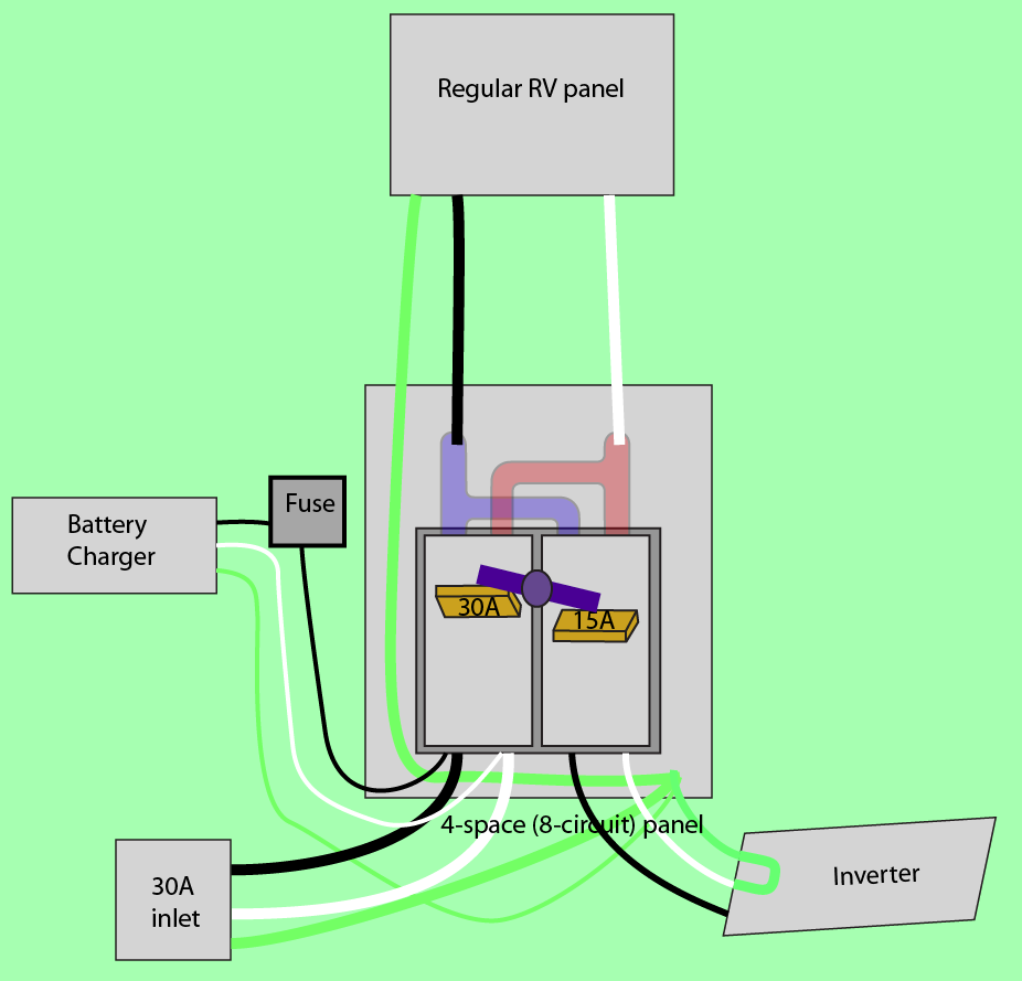
I recommend using an additional 4-space service panel/load center. This will use common off-the-shelf 2-pole breakers and interlock to switch both hot and neutral to your RV's regular service panel. This way, when on utility, the inverter's neutral-ground bond is disconnected from the house.

This will do something else cool for us: allow us to run the battery charger while on inverter, as long as utility power is present. That means you don't need to think about turning it on. It just does.

enter image description here

How to build it.

Use a 4-space/8-circuit micro-panel. Into it go two 2-pole breakers: one of them 30A (for the utility side) and the other is probably 15A (or whatever is appropriate for the inverter). Between the two breakers goes a "rocking interlock" that prevents both breakers from being on at once.

The breakers are "back-fed" (fed from the output side) to the common bus on the panel. That is then sent onward to the RV's existing AC panel.

Why do you need an interlock?

At the very least, the interlock is to keep your inverter from inadvertently backfeeding the power grid, if you bungled a switchover during an outage. Backfeeding can kill linemen repairing the lines.

But another big problem is neutral switching. It needs to be done. On utility, you have neutral and ground separated. On inverter, the inverter bonds neutral and ground, and this isn't disconnected by a normal switch. So the RV is bonding neutral and ground from the house.
The problem is, external failures (in the house) could cause loads outside the RV to path their return current via your RV (inverter's) neutral-ground bond. This can be far more amps that it was ever designed for. This is why we only bond neutral and ground in one place.

Doing it all with 1 panel

Since this is a 120V-only RV, you could actually make it happen in a single panel, by putting the branch circuits in the same panel as the interlock. However, since the panel is using its 2-pole functionality to switch neutral, all the branch circuit breakers will need to be 2-pole also - so they can tap neutral. This will gobble up breaker spaces at twice the rate.

Fortunately on these compact panels, you can usually use tandem (or in this case quadplex breakers). I would avoid small GE panels here*.

The switched neutral also makes GFCI and AFCI breakers out of the question, but you can always put them at the first receptacle.

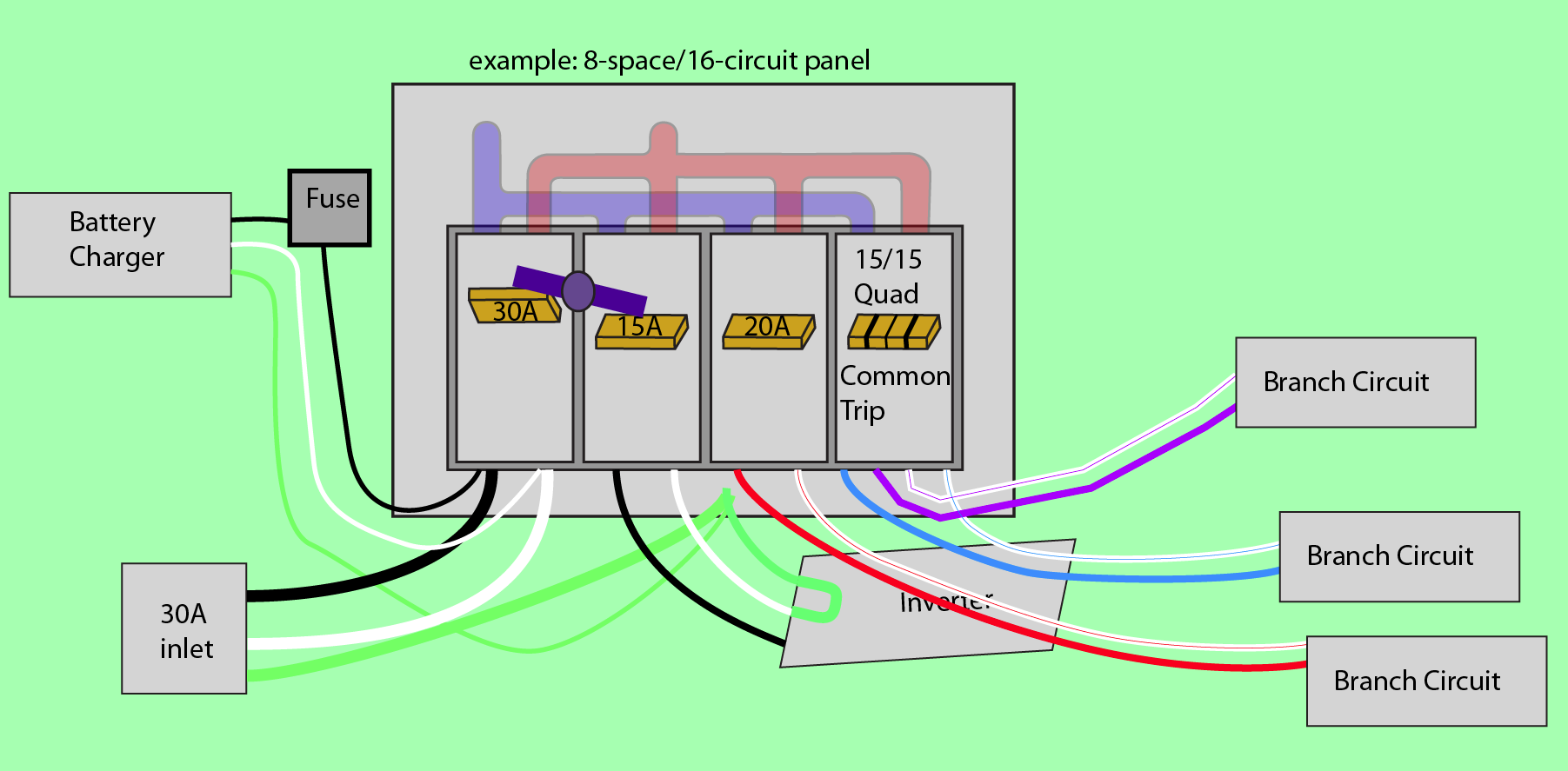
enter image description here

8 spaces for clarity. Pick any panel size you want. Grounds omitted for clarity. Note how every circuit taps neutral. Also note "outer/inner" way you tap a quadplex. Not illustrated: outer handle-ties on the quadplex.

Branch circuit wire colors for clarity; feel free to use black/white.

As long as you wire your grounds, and have 1 (temporary?) receptacle on each circuit, you can use a common 3-light tester to make sure you didn't accidentally exchange hot and neutral on the breaker.

All the breakers must be common-trip. Why? Because you can't abide a situation where neutral trips, but hot does not trip. The circuit would be inoperative, and seem dead, but would be live.


* unless you're very clear on how GE's double-stuff (thin/narrow) 2-pole breakers work - they're not like quads at all). With small panels, you'll find you can't support as many 2-pole breakers as you thought you could!

5
  • That looks simple enough :) Now to find a really small subpanel to put the interlock into and find a place to put it in my little teardrop RV. Commented Aug 26, 2021 at 12:23
  • @SamCarleton Well I'm having you use a separate 4-space panel, but you could do it in one panel. See my upcoming edit. Commented Aug 26, 2021 at 20:15
  • Oh, I am so sorry, I wasn't real clear. I am adding this to a really small teardrop camper that already has this All-in-one panel: progressivedyn.com/pd4100-series I am having to find space to put the inverter (I am going to go with the Victron MultiPlus 800), there simply isn't a good place to but another box. Commented Aug 26, 2021 at 21:47
  • @SamCarleton drat... My line of thinking was you could replace your previous choice of AC panelboard. Yeah, you probably should've mentioned all that lol. That's the trouble with all-in-ones lol. My original concept could be replaced by a UL listed 30A rated DPDT switch in proper enclosure, which could be as small as 2x4".... but that's industrial exotica. I was focusing on picking stuff your local Home Depot stocks. (And that's legal of course). Commented Aug 27, 2021 at 0:02
  • And as far as powering the battery charger discretely i.e. not in the panel, easy peasy... the black and white wires coming out of the DC section are the battery charger leads, and can be fed from anywhere you please, doesn't have to go in that 3-space panel. Commented Aug 27, 2021 at 0:03
2

There are inverter chargers that have this functionality built in that would go between your incoming shore power and the AC panel. They automatically switch between shore and battery power, if shore is plugged in then it passes through the inverter to the panel and charges the battery automatically.

Victron example of an inverter charger www.amazon.com/Programmed-Victron-MultiPlus-Inverter-Charger/dp/B08QTT6JTL

2
  • 1
    Yeah, a multimode inverter-charger is generally the best all-around solution to the problem -- Harper's solution is basically a legal/safe quick-hack for the OP's situation Commented Aug 26, 2021 at 3:47
  • I totally agree I would LOVE to have that unit, but there are a few problems. See my added comments above on what those are. Commented Aug 26, 2021 at 12:08
1

RVs are tricky beasts because a single unit may be used in different contexts; fixing the wiring so that it automatically satisfies electrical code requirements of each context is a tricky thing to do. The RV can act like:

  1. A subpanel. When connected to shore power the RV and its distribution center should be wired like an ordinary subpanel. It should use a 3-wire (20/30 amp) or 4-wire (50 amp) shore power connection; there should be no bond between neutral and ground in the RV. Usually there are batteries to be charged; it makes sense that the charger would connect to one of the circuits on that distribution center.
  2. A separately derived system. When AC loads are powered by an inverter and the RV has no electrical connection to a larger electrical grid then a neutral-ground bond is needed inside the RV. Some inverters automatically make and break the neutral-ground bond. Also there's the challenge that brought you here: how to avoid using inverter AC power to charge the battery that's powering the inverter.
  3. A separately derived system.. kinda. When the RV is powered by a portable generator through the shore power cord it's still a separately derived system and a neutral-ground bond is needed. But the inverter won't provide the bond in this condition and many generators don't either (the Honda EU series, for instance).

There are, of course, myriad valid ways of dealing with these issues. There are a number of choices to be made; each selection narrows the field of options for the remaining choices.

AC Power Source Selection

One detail not mentioned in the question is how the switching between shore power and inverter power will be accomplished.

  1. Cord-and-plug transfer: To use inverter power the shore power cord could simply be plugged to one of the receptacles on the inverter. (If the inverter has hardwire output, wire a single receptacle to it.)
  2. Manual transfer: The shore power cord and the inverter output could be hard wired to a manual switch. The hot wire(s) must be switched; switching the neutral and ground wires may be optional depending on how the neutral-ground bond is dealt with. So, a 1-, 2-, or more-pole switch might be needed.
  3. Automatic transfer: very similar to manual transfer except that the switch operates automatically based on some criteria.

Benefits of the cord-and-plug transfer method include that it's very easy to understand and to build correctly, and it's low cost. It provides a nice hook for automatically disabling the charger too: assuming the inverter has two output receptacles, use the second one to activate a relay which shuts off the power to the charger. A diagram might help:

           +-> Shore power -> Panel -> Relay -> Charger
           |                            ^
Inverter --+-> -------------------------+

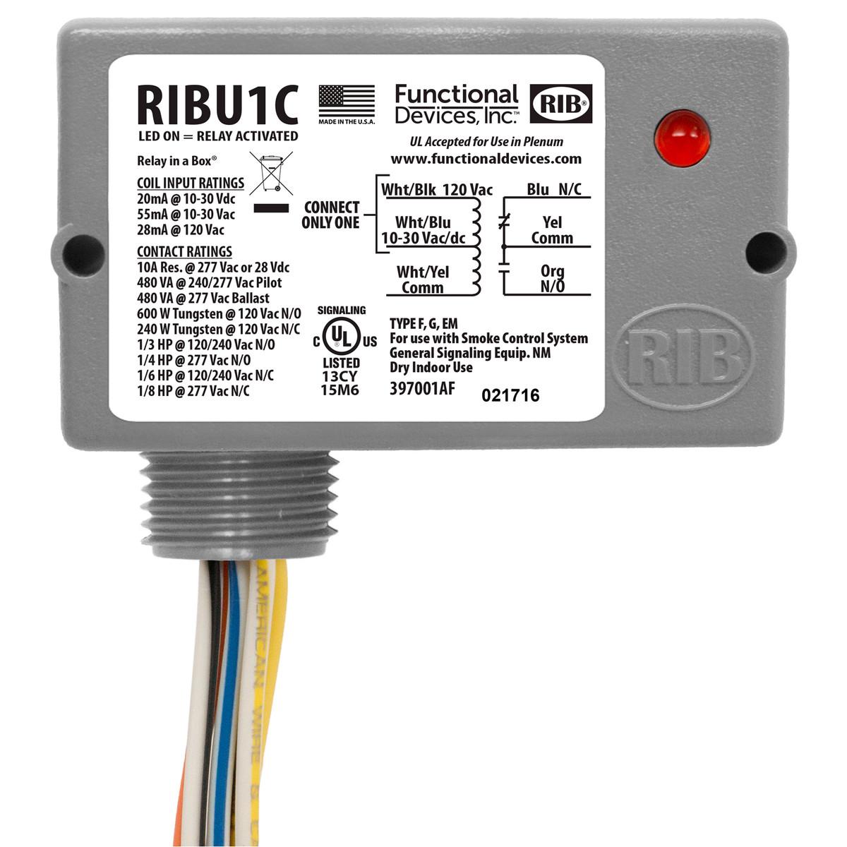
A device such as this Functional Devices RIBU1C will probably do nicely. Its coil inputs can be wired directly to the 120 volt output of the inverter; its normally closed contacts can be wired in series with the charger. When the relay coil is powered it'll break the circuit on the NC contacts, thus turning off the charger.

Functional Devices RIBU1C

Neutral-ground bond

Another benefit of the cord-and-plug transfer method is that it makes it easy to do the right thing for the neutral-ground bond. If the inverter makes the bond automatically then you don't have to do anything extra. If it doesn't make the bond automatically, you can create one by:

  1. Get a 3-prong replacement cord end and install a 12 gauge jumper wire between its ground and neutral terminals. Plug that into a spare receptacle on the inverter.
  2. If the inverter is the hard-wire type, tie ground and neutral together at the inverter or at the receptacle that you hard-wired to it.

A nice side benefit of #1 is that, if you happen to have a generator that does not provide a neutral-ground bond, then when using the generator you can grab that "bonding plug" off the inverter and plug it to a spare socket on the generator instead.

2
  • Ok, so you bring up grounding. Something I know little to nothing about, but your post highlighted the fact that I NEED to become knowledgeable about this to wire things up corectly. Can you point me to any sources that will educate me on the topic? Commented Aug 26, 2021 at 12:24
  • Mike Sokol at No Shock Zone has written extensively about electrical safety in the RV, marine, and theater contexts. I was introduced to the idea of the "bonding plug" mentioned in my answer through his article Generator Ground-Neutral Bonding.
    – Greg Hill
    Commented Aug 26, 2021 at 17:13
1

You have some misconceptions about the MultiPlus. This summer I've installed a 24/3000/70 model and became intimately familiar with its capabilities so I'll clear up a couple points for you.

Looking at the data sheet for the MultiPlus 500-2000 VA models we see the 500-1600 models have a 16 A transfer switch. This means that when shore power is connected the MultiPlus will pass up to 16 amps from shore power through itself and on to your AC distribution panel (not 650 W as you had thought).

The 650 W limit is continuous inverter power at 40 degrees C ambient. Because the 800 VA and larger MultiPlus devices offer PowerAssist, this means that if you're connected to shore power you could actually draw up to the full 16 A of transfer switch capacity plus the 650 W of inverter capacity at the MultiPlus output -- a total of about 21 A. When the load dropped below 16A the MultiPlus would automatically resume charging the battery bank. This PowerAssist feature would come in handy if you happened to have the RV powered from a generator and wanted to run your air conditioner but the generator alone isn't quite powerful enough to start the air conditioner.

It isn't necessary to have a massive battery bank with this or the larger MultiPlus models. The primary concern is to avoid drawing excessive current from the battery bank. "Excessive" varies according to the Ah capacity of the bank and its chemistry. According to a chart given there, a battery with lead chemistry might support 2C or higher discharge rate. If you had a 100 Ah battery and wanted to allow a 2C discharge rate that's 200 A allowed, which from a 12 V battery is 2400 W. So it wouldn't be unreasonable to choose a 2000 VA MultiPlus. A nice benefit of choosing the 12/2000/80 model is that you get an upgrade to 35 A transfer switch instead of 16 A with the 500-1600 VA models.

There's one other thing to consider: split the AC power system. Wire it so that heavier loads (air conditioning, microwave, water heater) go through a breaker panel that is fed only from shore power. Wire the other circuits to be fed from the MultiPlus -- its 16 A transfer capacity will easily handle all your smaller loads. An RV with a 50 A shore power hookup is likely to be built this way at the factory.

To convert yours to this topology, start with a normal 120/240 volt breaker panel. Connect the shore power hot to one of its input lugs and also to the MultiPlus AC input. Connect the MultiPlus AC output to the other hot input lug of the panel. Install single-pole breakers into the panel arranged so that they plug to either the shore-power bus or the MultiPlus bus.

2
  • Thank you so much, that is VERY helpful. I will seriously reconsider the MultiPlus. While I do like the idea of splitting the AC power system, in this tiny little camper it just isn't practical. It has the PROGRESSIVE DYNAMICS PD4135KW2B, a compact all in one system that combines both the AC and DC. I simply don't have space for another subpanel.. The RV in question is the Intech Luna, which just has enough room for the one queen size bed and has about 4 1/2 feet of head room inside. Very small, very tight. Commented Aug 26, 2021 at 18:31
  • P.S. 16 amp is plenty, I run the A/C unit when the RV is at home and plugged into my 15 amp line at the house. Commented Aug 26, 2021 at 18:35

Your Answer

By clicking “Post Your Answer”, you agree to our terms of service and acknowledge you have read our privacy policy.

Not the answer you're looking for? Browse other questions tagged or ask your own question.