10

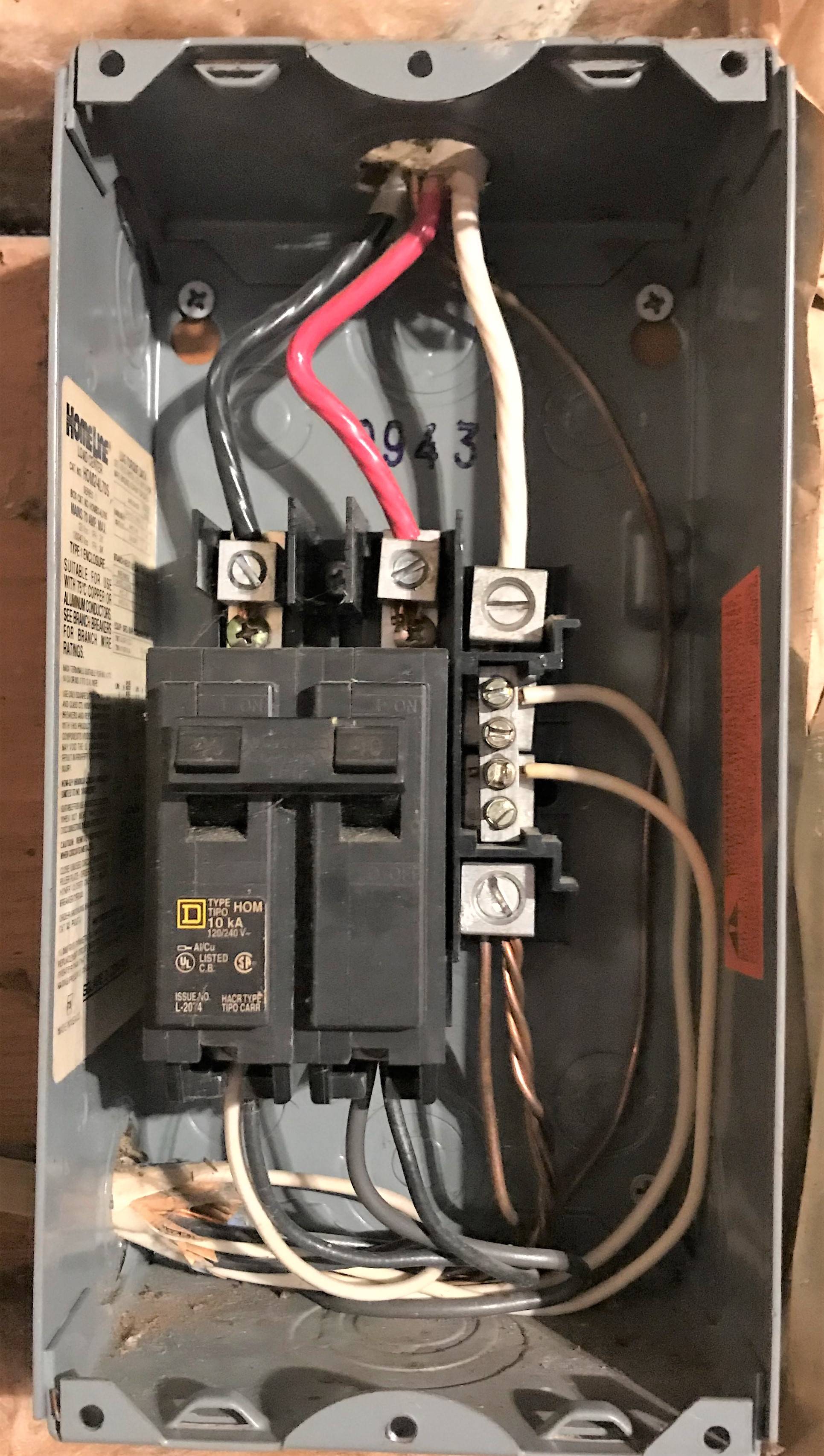
I recently bought a home and the garage has this sub panel that looks questionable to me. The garage has a circuit for 240v, and two other circuits that consists of two 120v wall outlets, and two 120v switched outlets. I do not know when this was all installed.

I do see that all the circuits run off a single 2 pole 40 amp breaker. The neutral and grounds are bonded as well in this panel. All the Romex in the garage is 12/2. The main panel is outside the home and the breaker for the garage is 40 amp.

I am a novice with home electrical but not a complete idiot and trying to learn. I dont plan on messing with any of this myself, just want to know how horrible this actually is.

Electrical panel

EDIT

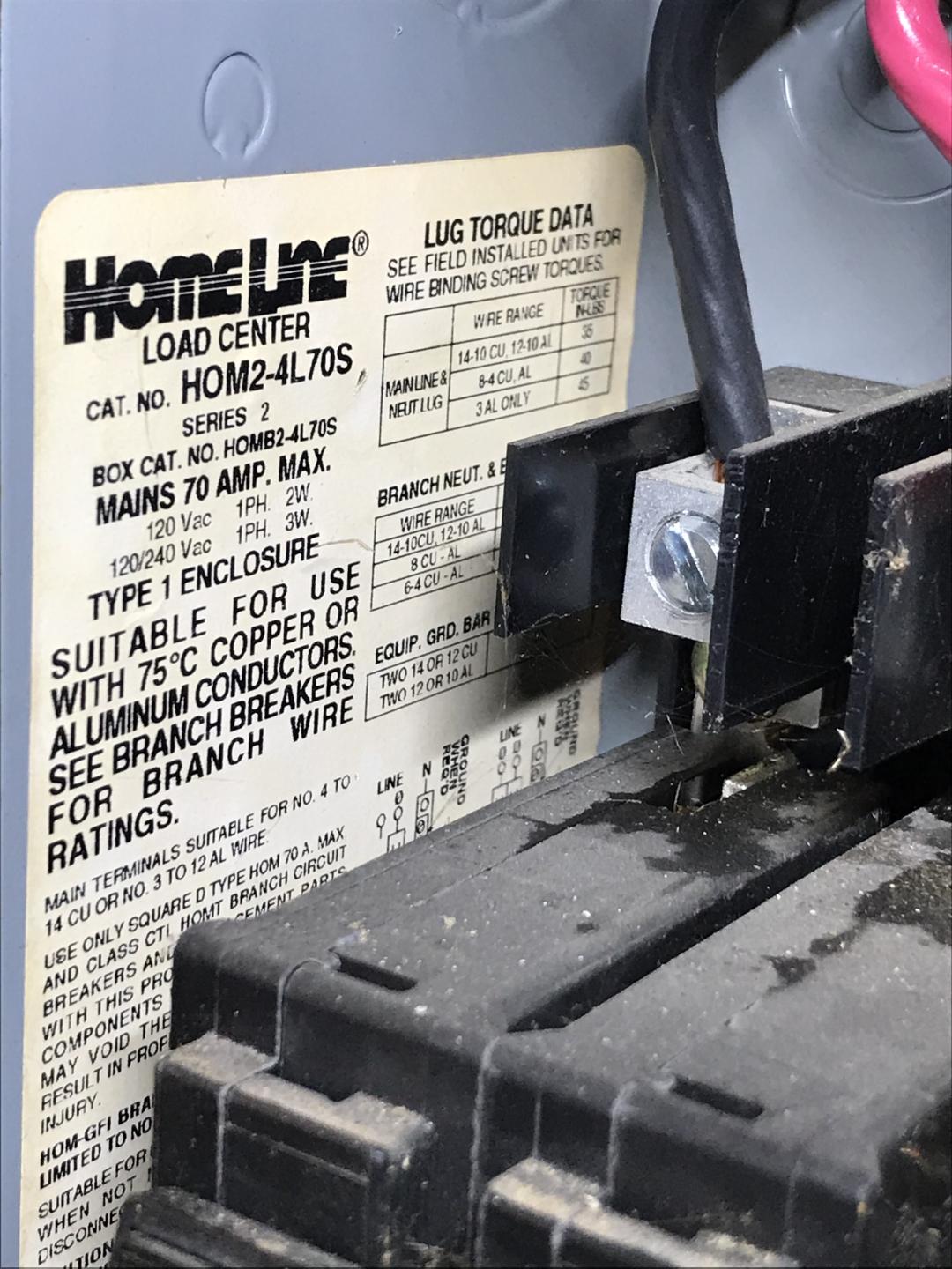
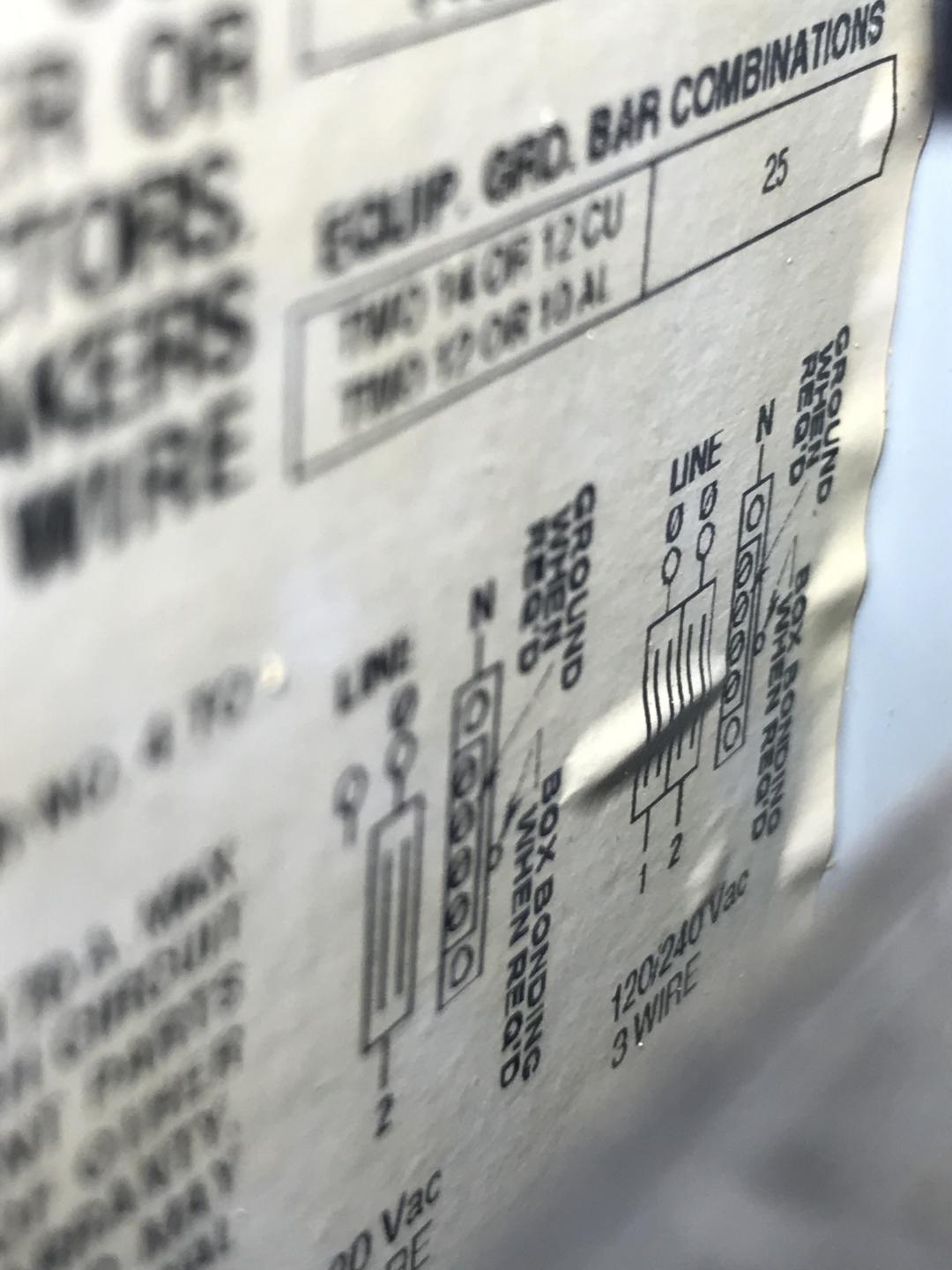
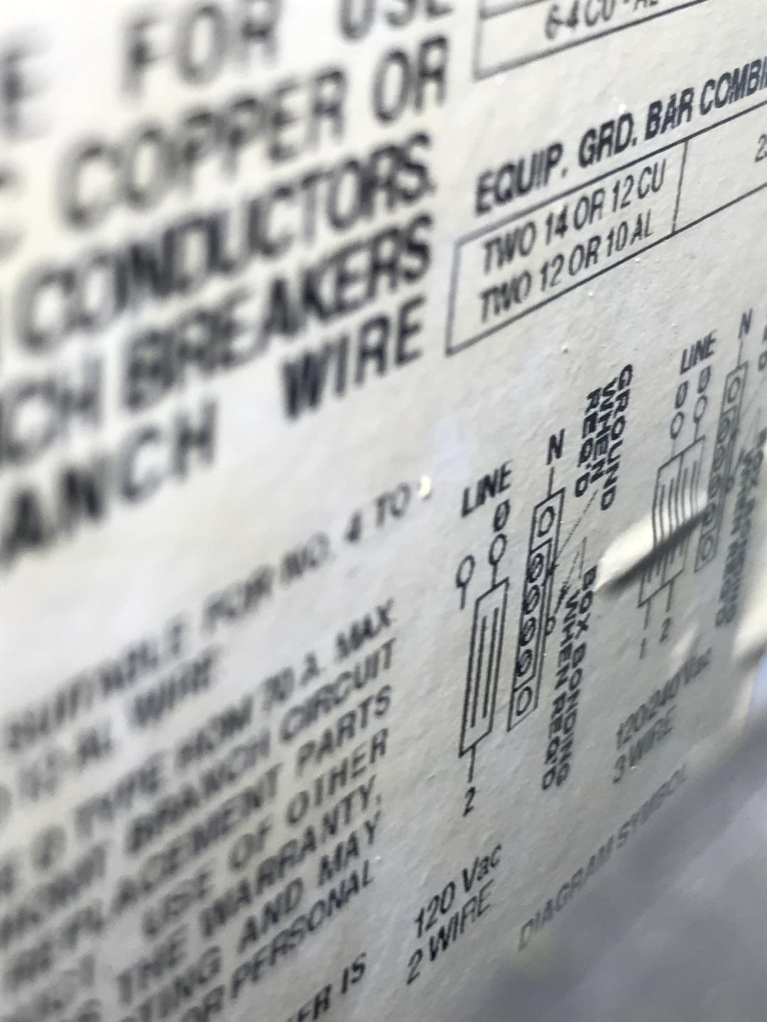
I have added below requested pics of the panel label. This is also a detached garage, ~20' away from the main panel on back of the house.

I really appreciate all the comments and suggestions and have learned alot just from this.

I suppose then my end goal is a subpanel upgrade, keep my current outlets but on two separate breakers (?) May just get rid of the existing 240v circuit and have a three foot 6 or 8/2 run to a 50amp breaker for the welder (?) Since the feed from the main panel is #8, I suppose Ill have to upgrade that moving forward? It is run overhead.

Trying to get a grasp on what I want/need before I call somebody to come out.

Panel2 Panel3 Panel4

4
  • Welcome! You're right: the situation pictured here is pretty bad (dangerous). But if you'd like an answer that helps you make a plan for fixing the problem, tell us more about how those three NM cables connect to the 240 and 120 volt outlets.
    – Greg Hill
    Commented Mar 25, 2021 at 19:58
  • Ill take a look and report back, thanks
    – rsg81800
    Commented Mar 25, 2021 at 21:33
  • 2
    @rsg81800 -- can you post a good, clear shot of the label on the inside left of the panel please? Also, is this an attached or a detached garage, and is replacing the wiring from the main panel to this subpanel an option? Commented Mar 25, 2021 at 22:41
  • 2
    Is that (white) tape on the feeder wires up top? If so, I would also remove it to inspect. With no bushings or grommets on the input it's likely that the person who made this mess also damaged the insulation on the sharp punch-out hole and then "fixed" it with tape. If that's the case, ideally you have enough length to cut the damaged portion away and remake the connection with good wire behind it.
    – J...
    Commented Mar 26, 2021 at 18:43

3 Answers 3

15

It is bad, more than a few violations here if I understand what is being fed. First violation no clamps /bushings coming into the panel 2 places. Next a 40 amp breaker feeding #12 possibly 14 awg wire 4 places 4 ground wires under 1 lug (I believe square D limits grounds to 2 wires) The neutral and ground issue would have been legal prior to 1999 If the garage is detached a separate additional grounding conductor would be required.

I would highly recommend this getting fixed sooner than later and the ground neutral issue is the least of the issues because if the other things were not a problem and built pre99 it would be ok.

Note if you can turn off a breaker inside the house It would be an easy fix with a 60a sub panel with a minimum of 4 circuits (go bigger) 60 amp panel 4 circuits 36$ or jump up to a 125 amp panel 12 circuits for 40$ (4 $ more double the capability and triple the circuits)

You use the existing 40 amp breaker in the house. Purchase the new sub Purchase 1 240v breaker 20 amp? Guessing on the wire size Purchase 2 120v breakers 15 or 20 amp 12 awg wire 20 amp , 14 awg wire 15 amp the wire size is stamped on the cable sheath. 4 clamps

The clamps go in the knockouts the 3 circuits out each go through a clamp 1/2” The input through a larger clamp 3/4” Terminate the 2 hots neutral and grounds and do not install the bond screw or remove it so the ground and neutrals will be isolated.

Connect the existing 240v circuit black white on the double pole breaker and ground. Connect each of the 120v blacks to there breaker Then the grounds on the ground buss neutrals on the isolated neutral buss

If it is a detached garage a separate ground rod needs to be added use a 8’ rod or pair of rods at least 6’ apart connected with #6 copper wire.

That’s it turn things on and know you eliminated a major fire and safety hazard and have a little room to grow before a larger feeder would be needed.

This can be done with the existing wires a larger box should make it easy but a wire or 2 may be short. Make sure the feeder fits first. Then add small wires and splice in the panel as needed it’s code compliant.

5
  • 1
    This is great info, thanks! Definitely going to look into correcting this. I want to run my TIG welder, which requires 40amp breaker for 120v, and 50amp for 240v. (dual voltage welder) So ill have to look into what will be needed to make those changes as well. Any thought on that?
    – rsg81800
    Commented Mar 25, 2021 at 21:37
  • I would guess your feed is a #8 but if it is larger you may be able to put a larger breaker in at the main. that’s why going with the bigger 125 amp panel would be a minimum for me that would be 8 circuits planned so maybe even bigger or more spaces. A larger 4 wire feeder and breaker and you are ready to toss in a 50 amp breaker for the welder with plans like that jump the feeder to at least 80 amp (since we don’t really know the existing loads but know they haven’t melted the small branch circuit insulation you can see where a even larger service could be used go as big as you can.
    – Ed Beal
    Commented Mar 25, 2021 at 21:49
  • @rsg81800 -- can you get us that photo of the label on the inside left of said panel please? Commented Mar 27, 2021 at 0:32
  • @rsg81800 -- are there 3 wires or 4 in the overhead cable between the two buildings? Commented Mar 27, 2021 at 3:09
  • There are four. Two hot, one neutral, and bare ground
    – rsg81800
    Commented Mar 27, 2021 at 4:23
7

Additional violations:

The breakers are double-tapped, yet they are the older HOM breakers that are not listed for 2 wires per tap.

If you can downgrade the 240V circuit to 15A or 20A receptacles (NEMA 6), you'd have a "Multi-wire branch circuit" with mixed 120V and 240V loads. That would be fine with a 20A 2-pole breaker at that point, and the smaller HOM breakers accept 2 wires, so that would legitimize the breaker double-tap.

There's no ground bar. There's 1 lug which appears to be part of the neutral bar, and that is quad-tapped for 4 ground wires, which doesn't even work. #1 dissimilar wire sizes isn't going to work, #2 the general idea of twisting a bunch of grounds together to imitate a stranded wire doesn't work, and #3 that lug doesn't allow multiple wires. Get a proper ground bar. That will separate neutrals and grounds.

Or alternately, since there are only 3 neutrals I would just wire-nut all the neutrals together, install a neutral-ground bond and use the bar for grounds.

As Ed Beal often points out, a 3-wire connection was allowed prior to NEC 1999, but this is a 4-wire connection. That concession was to reduce wire cost and avoid wasting the remaining supply of /3 no-ground cable. For instance it was always illegal to use /2+ground cable as your 3 wires.

Regardless, this work is not "grandfathered" into pre-1999 Code for two reasons. Work that violated Code at the time is not grandfathered. And to defend grandfathering, you need documentation of when it was done - i.e. permits. No permit was pulled here.

This panel is like safety theater. All the cost of doing it right, but no safer than gobbing all the wires together with wire nuts under an old soup can.

5
  • Well, more precisely, it's the wrong size HOM breaker for a doubletap (40A+ HOM breakers don't support it, even when brand new) Commented Mar 26, 2021 at 11:41
  • Depending on year built no ground bar was required.
    – Ed Beal
    Commented Mar 26, 2021 at 14:49
  • @EdBeal Even when separate neutral and ground was run to the outbuilding? But yes, I'm more concerned with the double?quad? tapping of the large lug, which will only be rated for 1 wire. Ironically if someone triple-tapped one of the small lugs with grounds, that is usually approved! Commented Mar 26, 2021 at 17:16
  • @ThreePhaseEel Yeah, reading it naked it really looked like a 30. I pulled it into photoshop and yeah, "40" seems more apparent. Wow, this whole thing was just safety theater. They utterly defeated every safety appliance, and are just using the panel as a splice block. Commented Mar 26, 2021 at 17:22
  • @ Harper only a few panels allow 3 terminations at the grounding buss that one has 4 , all things I brought up on my original answer.
    – Ed Beal
    Commented Mar 26, 2021 at 17:28
3

It's a mess in there alright

What you have there is a right mess:

  • No cable-clamps on either knockout
  • What looks to be insufficient jacket protrusion into the box
  • 20A circuits double-tapped off a 40A breaker that only supports one wire per lug
  • A box that isn't connected to ground at all
  • And neutrals and grounds slobbered together onto the same bar

Your first step is to clean up the obvious problems. The good news is that this box can accept tandem breakers, so replacing the existing HOM240 with a HOMT2020220, adding a PK3GTA1 grounding bar to the enclosure, and moving the grounding wires over to said bar will fix the most glaring issues here.

The cable-clamping problems are a bit tougher due to the lack of jacket protrusion at the top and the overstuffed KO on the left, though. The good news is since this is exposed work and you'll be pulling the load-side wiring apart anyway, you can use a "new work" NM connector fit for a 1" KO and rated for 3 12/2 cables, such as an Arlington NM842, to get those NM cables in the box, with a &frac34"; NM connector in the top knockout to fit that 8/3 feeder cable in there provided that you can get a bit of jacket into the box for the NM connector to grab.

If that's not an option, then you'll have to shift the breaker box to the right and add a 4" square junction box next to it, fitted using a chase-nipple, locknut, and some 12AWG THHNs. The grounding wires from the load-side cables can terminate here to a grounding pigtail to said box, while the hots and neutrals are spliced through, and the cables clamped to the box using standard NM clamps.

Your Answer

By clicking “Post Your Answer”, you agree to our terms of service and acknowledge you have read our privacy policy.

Not the answer you're looking for? Browse other questions tagged or ask your own question.