1

My bathroom has a light/fan combo fixture. The wall receptacle previously had:

  1. Single pole switch to control the light (on/off)
  2. Single pole switch to control the fan (on/off)
  3. Mechanical timer switch for the fan

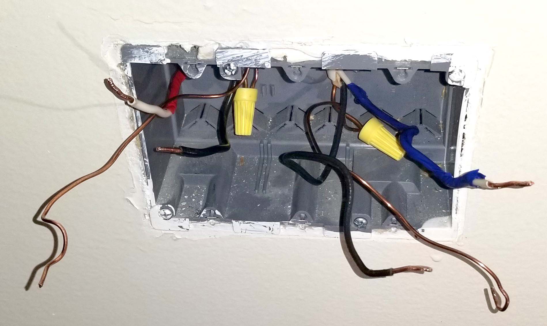
There are only two 12/2 cables coming into the box (I assume one for fan, one for light). I removed the old switches because I just wanted to replace with a new rocker switch for the light and a new timer for the fan (no longer 2 switches for fan). I believe the two fan switches before were tied together to you could either leave the fan on/off with one switch or set a timer for it with another. Unfortunately, I didn't pay close enough attention to how it was wired before and am at a loss for how to wire this correctly.

Here is a picture of the wires in the receptacle:

enter image description here

I want to connect a single pole switch for the light on the right side (has a ground nut and two brass nuts) and an Eaton 9590AW 5-Button Preset Minute Timer for the fan (has a green ground wire, a red wire, and a black wire sticking out of the back). The timer supposedly does not need a neutral wire.

Any input on how I should wire this? When I just try to wire the timer switch to the cable on the left and the light switch to the cable on the right, I get no power to the fixture. When I try combining wires with pigtails, sometimes I can get light to operate but either the fan is always on or the fan has no power. I cannot seem to figure out how to wire the light and the fan separately so that I can use the timer feature for the fan.

2
  • Can you post photos of the insides of the light-fixture and fan boxes please? Commented Jan 16, 2021 at 23:37
  • Stop experimenting! Your method is "try stuff til something works", however there are many combinations that will "work" and then will kill you. Also in the future don't unhook everything (in fact don't unhook anything before taking a picture), e.g. replace one switch at a time. Commented Jan 17, 2021 at 19:22

1 Answer 1

1

Each of these cables is a switch loop. In theory, the taped white (red or blue) is the always-hot wire and the black wire is the switched-hot. However, it could be the reverse. There are two easy ways to tell:

  • Open up the fan and light and see which wire is connected to another black (= always hot) and which is connected to the fan or light (= switched hot)
  • With all the wires carefully separated, turn the breaker back on and see which wires show hot with a non-contact tester.

Once you know which wires are always hot and which wires are switched hot:

  • For a standard "both screws are the same, nothing fancy" light switch, connect one insulated wire to one screw, the other insulated wire to the other screw, bare ground to the green screw and done.
  • For the timer:
    • Connect (wire nut) bare ground to green
    • Connect (wire nut) always-hot wire to black
    • Connect (wire nut) switched-hot wire to red
2
  • I tried wiring a standard switch to one 12/2 cable and the timer switch to the other 12/2 cable (essentially, both switches completely separate in the wall receptacle), but I don't get power to either the fan or the light. Do I need to somehow connect wire between the two cables or the two switches?
    – Dave
    Commented Jan 16, 2021 at 23:48
  • If you don't already have, get a set of testers - non-contact and multimeter like this and you should find one wire in each cable hot and ~ 120V between the hot & ground and 0V between the other wire and ground. If that's the case, switches should work. If that's not the case, we need more info by opening the fan & light boxes to check the wiring. Commented Jan 17, 2021 at 0:04

Your Answer

By clicking “Post Your Answer”, you agree to our terms of service and acknowledge you have read our privacy policy.

Not the answer you're looking for? Browse other questions tagged or ask your own question.