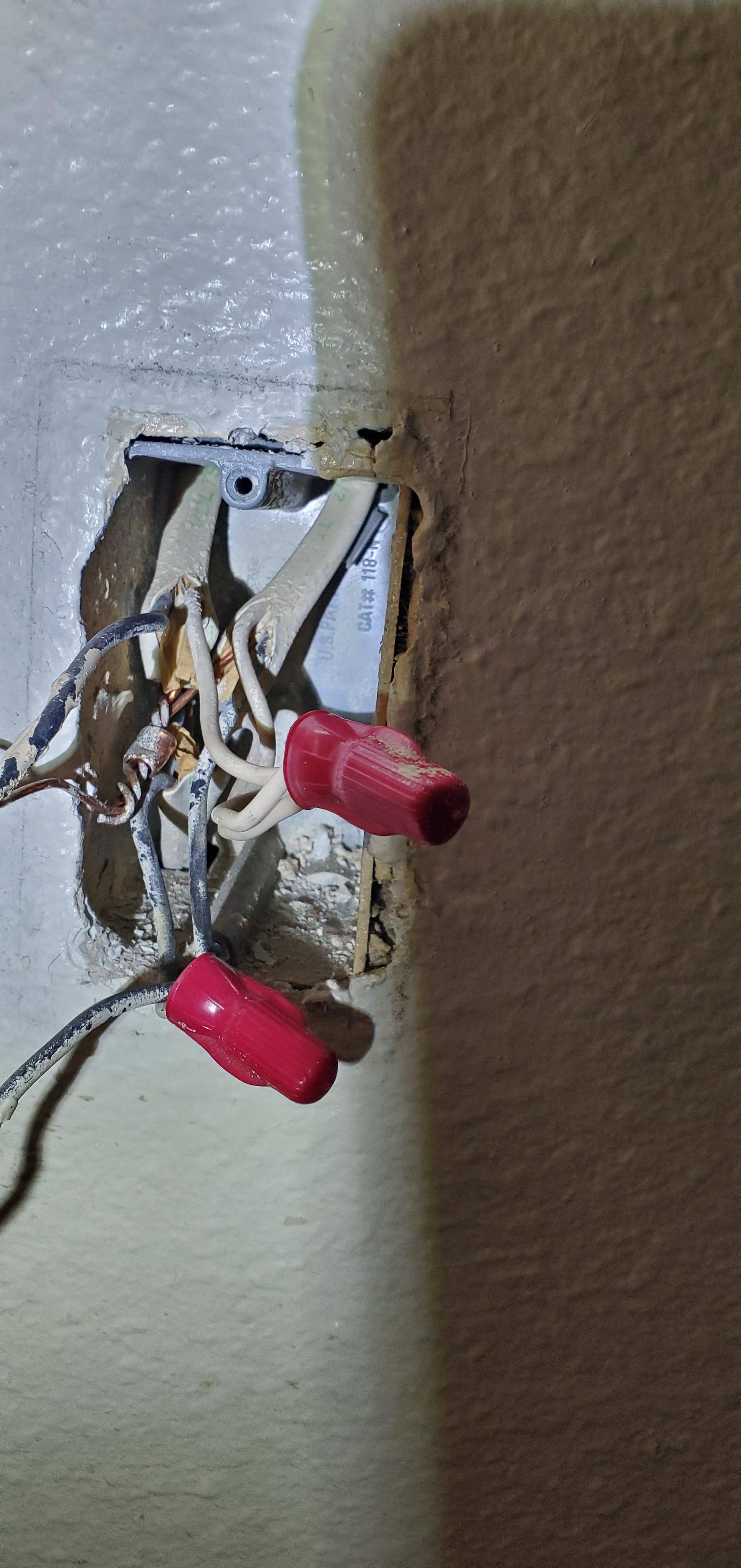
I'm trying to replace a couple of old switches with new dimmer switches that have the wifi capability. I understand electronics fairly well and have done basic electrical work around the house before. But this situation has me a bit confused. I have 3 wires. The 3 grounds are "pig tailed" the 3 neutrals (white wires)are tied together with an wire twist. 2 blacks are pig tailed and one is alone. The old switch is single pole and the black pigtail and the single black went into the back. Ground was around the screw. When I connected the new switch, it required the neutral wire. So after connecting the 2 sets of black wires and neutral into the switch I tries each neutral individually but no luck. One of the neutral would light up the switch but not the light. Later I discovered that by disconnecting the neutrals I lost power to my outlets. The switches I'm replacing are in the bathrooms and the outlets were in the bathroom and one in a bedroom adjacent to the bathroom. The idea is to pigtail the neutrals and connect the tail to the switch. This way it won't interrupt the circuit and provides my neutral for the new switch. Does this make sense? Thank you for the feedback.
2 Answers
Yes, you're on the right track: the three neutrals should remain bundled together. Simply add the neutral from the wifi switch into that group.
-
Thank you. Is there a reason why the light switch is hooked up to the outlets? The switch does not control the outlets neither is there a second switch for a 3 way. Just a bit confused about this. Thanks in advance. Commented Dec 17, 2019 at 23:52
-
@RaulPadilla I'm an amateur, so if someone contradicts me, I immediately concede that they are correct and I am wrong. That being said-- most likely you have a common neutral wire between your switch and your electrical outlets. Theoretically, one of the white neutral wires should have connected to a source location, and using it should have made your new switch work. I believe it daisy chains through the light switch to the outlets, and that is why disconnecting them caused the outlets to stop working. (Again, I welcome corrections by more knowledgeable persons) Commented Dec 19, 2019 at 16:28
The three cables are
- Always-hot and neutral from the service/supply panel
- Always-hot and neutral onward to other appliances
- Switched-hot and neutral to the lamp
(and we're ignoring equipment safety ground, because in mains electrical, it's a safety shield only. It's not a player in any capacity, electrically, until there is current leakage, in which case it provides a safety shield. The hot-neutral supply is wired the same as an isolated system, with no concept of "chassis ground" like you might find in a car. There is no equivalent in low voltage electronics.)
I am no fool, but I often need to work on panels some years later. As such, I am a huge fan of using tape or shrink-tube to re-mark hot wires based on their function. Keep in mind you can't re-mark amongst hots, neutrals and grounds, except white/gray (neutral) wires to be a hot, if it's in a cable. It works out nicely as a convention to use red (blue or yellow as alternates) for switched-hot. And I'm famous for double-yellows for 3-way travelers - they go on the brass screws after all.
So I would mark the switched-hot wires with red tape.
Here's an electronics question for you.
I'm going to say Vss instead of GND because in mains electrical, Ground is actually something else.
You have 5 volt Vcc (+) and Vss (-) going into a circuit. The Vss specifically comes from the power supply on a black wire, then goes three ways: to the Arduino controlling it, to the solid state relay, and to the lighting LEDs controlled by the relay.
You want to add an indicator LED to show when the Arduino has access to DC supply. You connect from Vcc through a resistor and the LED to Vss. However, there are four Vss wires. Which one do you use? The one to the power supply? The one to the Arduino? The one to the relay? Or the one to the lighting LED?
That's a trick question, of course; all four are already connected, and they need to stay connected. The additional Vss wire would be added to the group.
So it is with mains neutral. Neutral is analogous to Vss.
