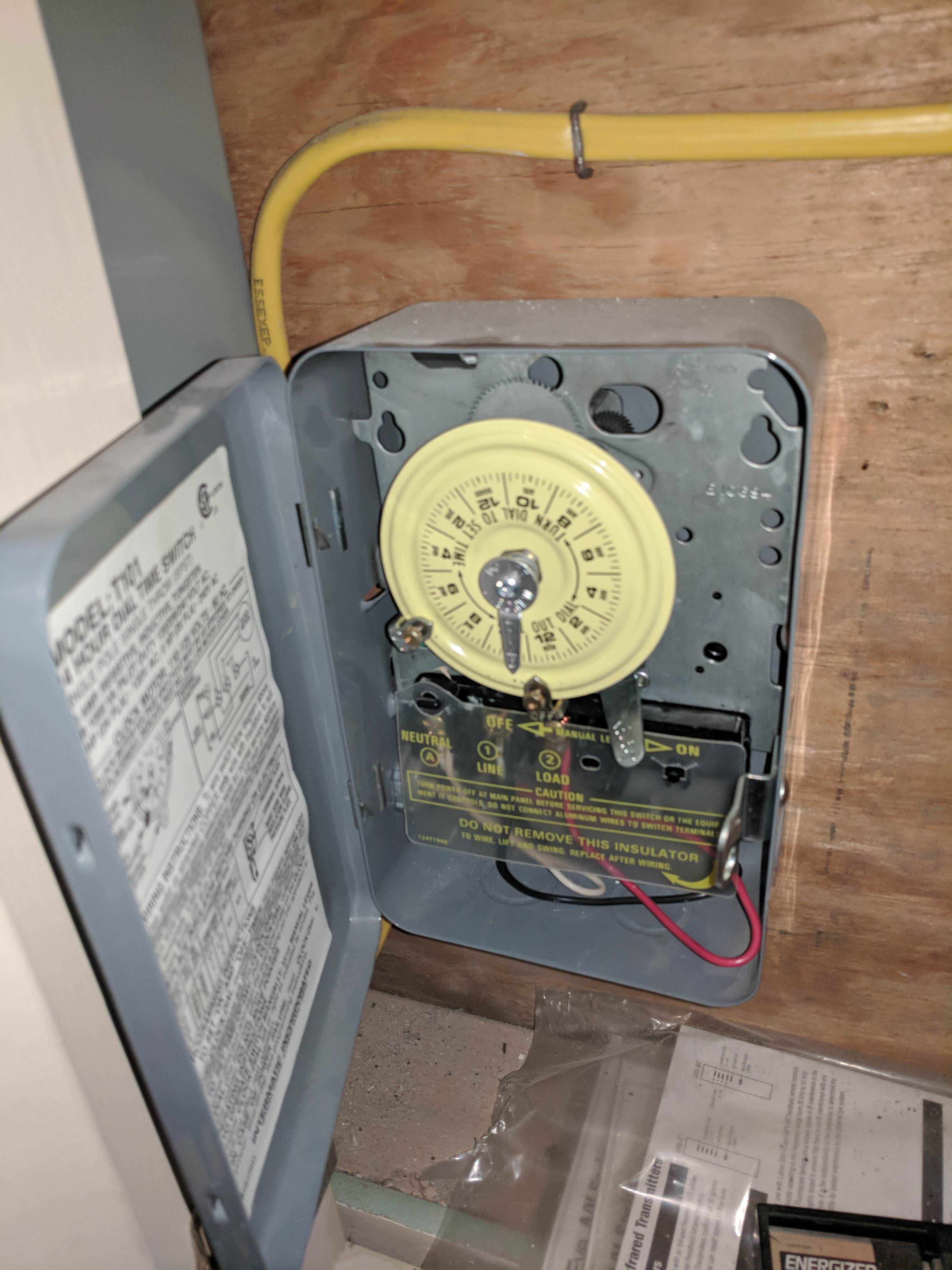
1

I have an outdoor light controlled by a pair of 3-way switches, A and B. The switch B is much closer to the light.

Here are the behaviors I observe.

During the day:
A: Up     B: Up or Down    Light:ON
A: Down   B: Up            Light:ON
A: Down   B: Down          Light:OFF

During the night:          Light:ON (regardless)

Also, believe that the light comes on at a certain hour. So it must be on a timer and not on a light sensor. However, I cannot locate the timer.

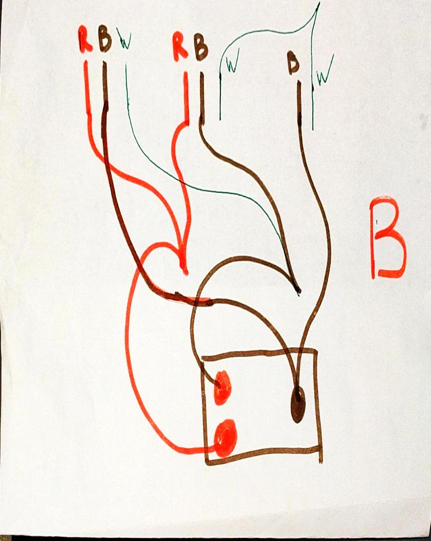
The wiring on switch B is attached.

I'm assuming I'm correct that the timer is involved. However, I still cannot make sense of the wiring and so I cannot figure out how to change it to make the three-way switches act normally during the day.

enter image description here

UPDATE: I've disconnected the wires and here's what discovered. The power comes via one of the 14/3 wires. The black is always hot. The red is hot during a few hours of the night (but not dusk to dawn. More like 1am-4am). Does this confirm that there's a timer somewhere along the way? What could it possibly look like?

UPDATE: Mystery solved: enter image description here

7
  • What about switch A? Which cable connects the switches? How is the light wired? Which cable connects switch B to the light? Which cable runs to the circuit breaker box? Commented May 10, 2018 at 3:55
  • You will need to trace the cables to determine how the switches, light, and power supply are connected. There are two general methods for tracing cables in house wiring, physical and electrical. The physical method consists of visually following the wiring, and is often impossible when the cables are inside finished walls. The electrical method requires disconnecting all the wires, sending a signal or voltage down one wire at a time, and detecting where it comes out. Commented May 10, 2018 at 3:59
  • Switch A is in a box with four other switches so I was hoping to avoid opening it up. I'm 99% sure that the power goes to switch A. I'm not able to reach the outdoor light since it's 3+ stories up.
    – Wynne
    Commented May 10, 2018 at 4:00
  • Can you see the outdoor light clearly? Could there be a photocell up there? - Maybe you can determine which cable runs to the light by applying power to it. Commented May 10, 2018 at 4:06
  • Are you really seeking to turn the light on during the day? What use is that? Or do you aim to turn it off by night? Any thoughts to going to a smart switch, then you can code any behavior you please. Commented May 10, 2018 at 13:53

1 Answer 1

1

If you look at the screws on the switch (if it is a new switch) there will be two silver screws and one black or gold screw. The silver screws are for the travelers and the black screws are for the line voltage coming in and the load voltage going out.

Start by shutting power off and taking the wires off each switch, separate the wires so they don't touch, then turn power back on and find the wire that is hot. If you don't have a meter you can get a tester at the hardware store.

Next attach the hot wire to one of the other wires from that switch and test the voltage on the other box. Then attach the hot wire to the other wire and test the voltage at the other box. These will be your travelers.

Cut the power and attach the travelers to the silver screws. This will leave on wire in each box that is your line (source voltage) and load (going to the fixture). Attach those wires to the black screw and you should be good.

0

Your Answer

By clicking “Post Your Answer”, you agree to our terms of service and acknowledge you have read our privacy policy.

Not the answer you're looking for? Browse other questions tagged or ask your own question.