1

The original owner of our house had this wired apparently and the outlet has never worked. Plugging a device in turns off the overhead light. Wife wants me to use vacation time off to fix, but I'm confused with the diagrams I've pulled up as they don't match the two wire setup nor the switch.

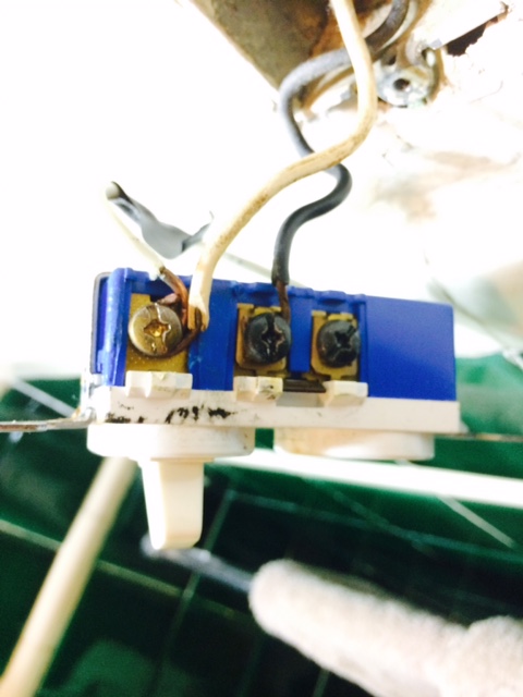
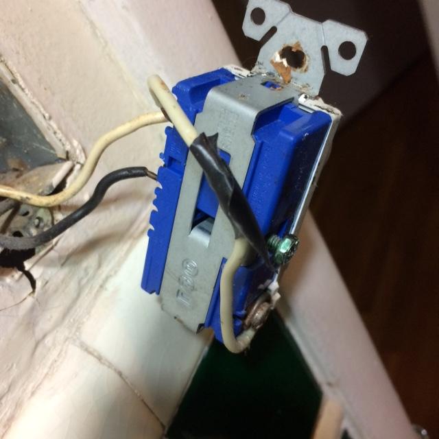
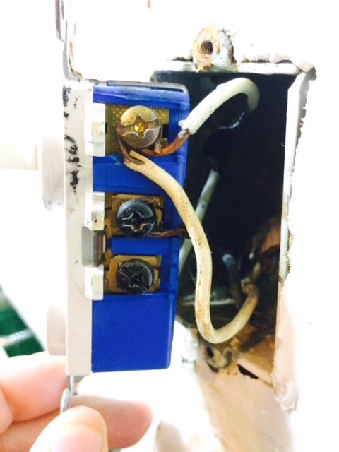
1)The black wire is connected currently to the first dark screw. 2)The white wire is connected to top screw with wire going around to the other side, bottom silver screw.

The tab seems in tact between dark wires. Light switch works, but the outlet does nothing, but if you plug in a device, turning the device off/on turns light off/on.

I just need outlet to work, doesn't matter if the has to be on. Thanks.

right side

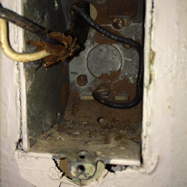
Left side close up back inside box

3
  • 1
    What is that other black wire in the back of the box? That doesnt look right.
    – Grant
    Commented Dec 31, 2014 at 19:33
  • 1
    @jlarm, can you post pics of the the light junction box opened up like your first post? Where does that black wire in the last picture go?
    – Brian Duke
    Commented Dec 31, 2014 at 23:13
  • I will in the morning. Thanks user3623501. I think it's supposed to be a ground.
    – jlarm
    Commented Jan 1, 2015 at 2:31

2 Answers 2

5

There doesn't appear to be a grounded (neutral) conductor in the box. Looks like it's a simple switch loop, that somebody tried installing a combination receptacle on. It looks like the black wire is an ungrounded (hot) conductor, and the white wire is a switched ungrounded (hot) conductor.

There's no way to add a receptacle here, unless you pull a grounded (neutral) conductor to the box.

The top black screw on the device (middle of side one), is the ungrounded (hot) conductor going to the switch. This screw is connected to the bottom black terminal via the copper tab, which provides power to the receptacle. The top black screw is also connected to the upper brass screw through the switch. When the switch is closed, electricity can flow "in through the black screw and "out" through the upper brass screw. This supplies switched power to the light fixture.

The middle screw on the other side of the device, appears to be a grounding screw. The lower screw is where the grounded (neutral) conductor should be attached. This provides the grounded (neutral) connection, which is required to make the receptacle function properly.

5
  • Isn't the wire at the back of the box the grounded wire? Can I pull of that one to get the ground?
    – jlarm
    Commented Dec 31, 2014 at 22:19
  • Can I use the wire at the back of the J box for a ground? Also, "The middle screw on the other side of the device, appears to be a grounding screw." Do you mean the side with three screws or two?
    – jlarm
    Commented Dec 31, 2014 at 22:28
  • "+1 Looks like a back-fed switch." Can you explain? Do I need a different switch?
    – jlarm
    Commented Dec 31, 2014 at 23:16
  • 2
    @jlarm, NO, you do not need a different switch. There is NO WAY to use a receptacle at this box without rewiring. Period. Whoever put that switch/receptacle combo there had absolutely no clue what they were doing. Commented Dec 31, 2014 at 23:59
  • 1
    @jlarm I would assume the wire in the back of the box is a grounding conductor, which should be extended to attach to the green screw (on the side of the switch with two screws) on the switch. The white wire that is connected from one side of the switch to the other, should be removed. There is no way with the current wiring for the receptacle to work properly or safely. Remove the combination device, and install a simple snap switch.
    – Tester101
    Commented Jan 1, 2015 at 0:13
2

Tester is spot on about the lack of a neutral conductor, all you have is a hot and switched, the outlet doesn't have the necessary wiring. You'll need to run another line with a neutral. If that line also contains another hot then you can break off the tab between the two hot screws and wire the bottom with the new hot/neutral. If that hot comes from a separate circuit (not recommended), be sure to label this outlet as having two circuits inside so someone doesn't accidentally electrocute themselves. The best option is to fish a 3 wire bundle (plus ground) from the fixture light that contains the hot, switched (red), and neutral.

If you continue to use the existing wiring, I'd also double check that it's really a ground wire in the back of the box (in black insulation). It's entirely possible that you have an electrified box, in other words an electrocution hazard.

In the current form, electricity goes in the hot screw, and if something is plugged in the receptacle with the switch in the off position, it goes through the device, out the "neutral" screw, into the switch hot wire to the light fixture, and from there through the light and into the proper neutral. When two devices are run in series, you get a drop in voltage which is why you see the light fixture go out. And when the switch is on, voltage will pass through the switch rather than through the outlet since it's the easier path for electricity, powering the light fixture but not the device.
Your Answer

By clicking “Post Your Answer”, you agree to our terms of service and acknowledge you have read our privacy policy.

Not the answer you're looking for? Browse other questions tagged or ask your own question.