0

I have a Nest Learning thermostat. Recently, it has caused a clicking sound to emanate from the furnace area whenever the system is powered off. I've determined this is due to the thermostat drawing insufficient power through the W1/Rc wires that it uses (2 wire heating-only system). Nest technical support recommends connecting a C wire, although I am also investigating if this is a possible battery issue. We are running our system for 1-2 hours a day, and our electrical parameters on the Nest device are all within the ranges recommended here: https://support.google.com/googlenest/answer/9241211?hl=en#zippy=%2Cpower

As I'm seeing a lot of recommendations to connect a C wire regardless for smart thermostats, I'd like to see if that is possible in my system. I do have 5 wires pulled through. I have taken pictures of the thermostat wires, along with the control board setup: https://photos.app.goo.gl/6zJfUfQsRQ2cDoTq6

Can anybody tell me if there is some way I could connect the loose blue or yellow wires to the board so that either one could function as a C wire?

2 Answers 2

1

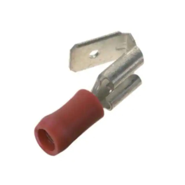
I'd get a "piggyback" crimp connector and use that to land the common C wire on the C terminal

Given that your board does not supply outgoing C terminals, we have only one sane place to tap C left, and that's at the terminal where it comes into the board from the transformer. However, we still need to be able to connect the incoming C wire to that terminal, so you'll need to use a ¼" "piggyback" crimp terminal rated for 18AWG wire crimped onto the end of the common C wire in your panel to leave room to land the C wire from the transformer (it'll look like the one shown below):

exemplar piggyback crimp terminal

3
  • If I knew this existed I would not have called connecting at this point "worst case". And to avoid the uncertainty of crimping to very thin wire, replace that yellow pigtail from the thermostats with a thicker one.
    – jay613
    Commented Mar 16, 2021 at 16:31
  • Got it, so I would be crimping the thin yellow pigtail wire (or a thicker replacement), into the insulated end, inserting the female end onto the JC terminal on the board, and then connecting the current thick yellow C wire from the transformer on the tab (that is a male connector), that is jutting out from the top of the top right of the image above?
    – tannranger
    Commented Mar 16, 2021 at 18:05
  • @tannranger -- convention calls for the blue wire to be used for C, but you have the right idea Commented Mar 17, 2021 at 2:01
0

It looks like all the yellows and blues from the thermostats were nutted together with an unconnected pigtail all ready and waiting to do this. So you just need to know where to connect that one loose wire.

Near the top left of the board are two yellow wires, the 24V supply, marked C and R. The top one is C. Worst case you'll have to connect there, though it will be a bit of a pain with that push-on connector. If you have a continuity tester the first place to check is pin 1 from any of the pump terminals along the bottom. My guess is they are all connected together and to C. Check that with a tester and I'd use one of those if so.

5
  • A concern though, according to the manual, those terminals only receive 24V when a thermostat is calling for heat, see 16/20: argocontrols.com/sites/default/files/AZ4CP%20AZ6CP%20IOM.pdf
    – tannranger
    Commented Mar 15, 2021 at 20:50
  • Wow! Did exactly as you said after confirming continuity from C terminal to pin 1 of the first pump terminal. After connecting the various loose wires (and again confirming continuity from C terminal to the twisted yellow wire bunch), looks like I'm getting healthy current to my Nest! photos.app.goo.gl/gvzbKsggB7mbJSj77
    – tannranger
    Commented Mar 15, 2021 at 21:29
  • The information on p16 confirms what I guessed from the sticker on the cover. A further guess is from the green color of the wires on pin 1. Not exactly scientific I admit. Hence you should confirm it with a continuity tester. My guess is that pin 1 is always connected to C and pin 2 is energized when called for. It could be the other way around, that would be an odd use of wire colors but sure. It could also be that pins 1 and 2 are both disconnected from anything when heat is not called for but that would be a bizarrely unnecessary way to complicate the control board.
    – jay613
    Commented Mar 15, 2021 at 21:38
  • Hmm. I guess one thing you might want to worry about is the combined current of one pump and 6 thermostats might be more than designed for the current path back from pin 1 to the transformer. Unlikely ... you would think a pump will draw orders of magnitude more than a thermostat. There's a tech support number on the last page of the manual ... call it!
    – jay613
    Commented Mar 15, 2021 at 21:45
  • We only have 1 thermostat hooked up, pulling max 200mA according to the display. If we ever hook up a second that pulls from the C wire that would definitely be something worth checking though, agreed.
    – tannranger
    Commented Mar 15, 2021 at 22:40

Your Answer

By clicking “Post Your Answer”, you agree to our terms of service and acknowledge you have read our privacy policy.

Not the answer you're looking for? Browse other questions tagged or ask your own question.