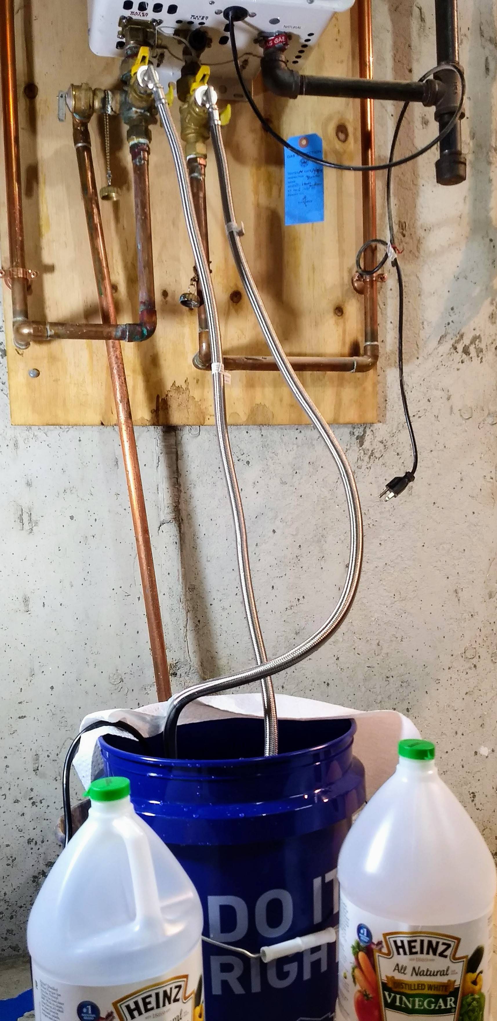
The schematic is most directly applicable to a heater installed with ordinary two-way valves. Your heater is installed with a service valve kit which has three-way valves and it doesn't quite match the document. Still, the flush procedure is the same.
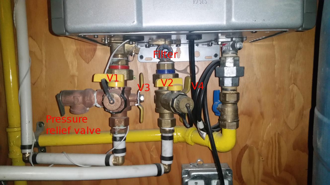
Please refer to the photo of my heater's valves below. The yellow handles are the valves; the round pieces on the front, which you had guessed might be V1 and V2, are only caps to keep debris out of the flush ports.

Valves V1 and V2 control flow through the service ports. These should normally be in the closed position (handles pointing to the left) -- don't rely on the service port caps to prevent water leaks! Valves V3 and V4 are three-way selector valves. When the handle is oriented vertically the heater is connected to the house and supply water piping. When the handle is oriented horizontally the heater is connected to the flush ports.
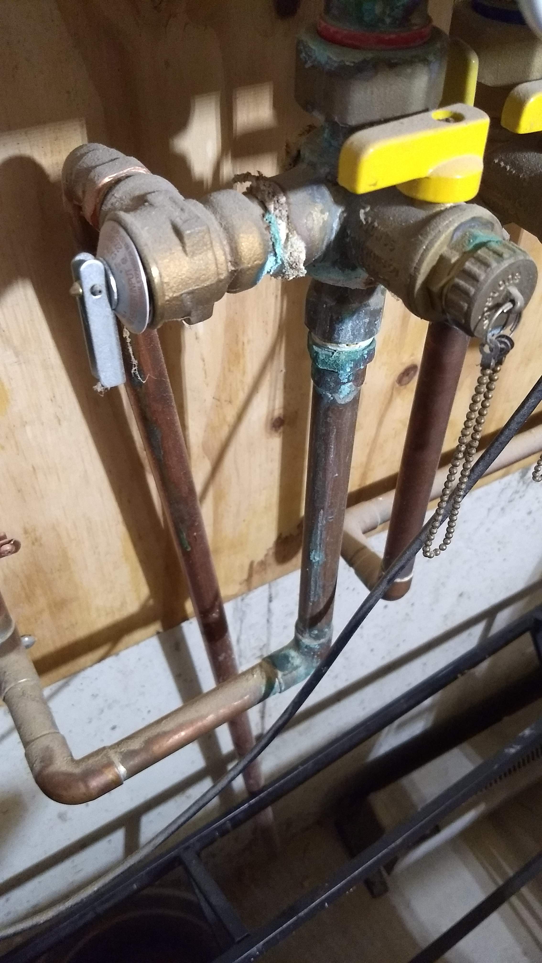
If your valves are like mine, V3 and V4 are extremely difficult to turn. On mine I would rotate the lower part of the handle toward the wall to change from normal operation to service/flush mode. You can confirm whether yours turn the same way by checking the position of the limiter tab where the silvery steel handle touches against the cast brass valve body.


