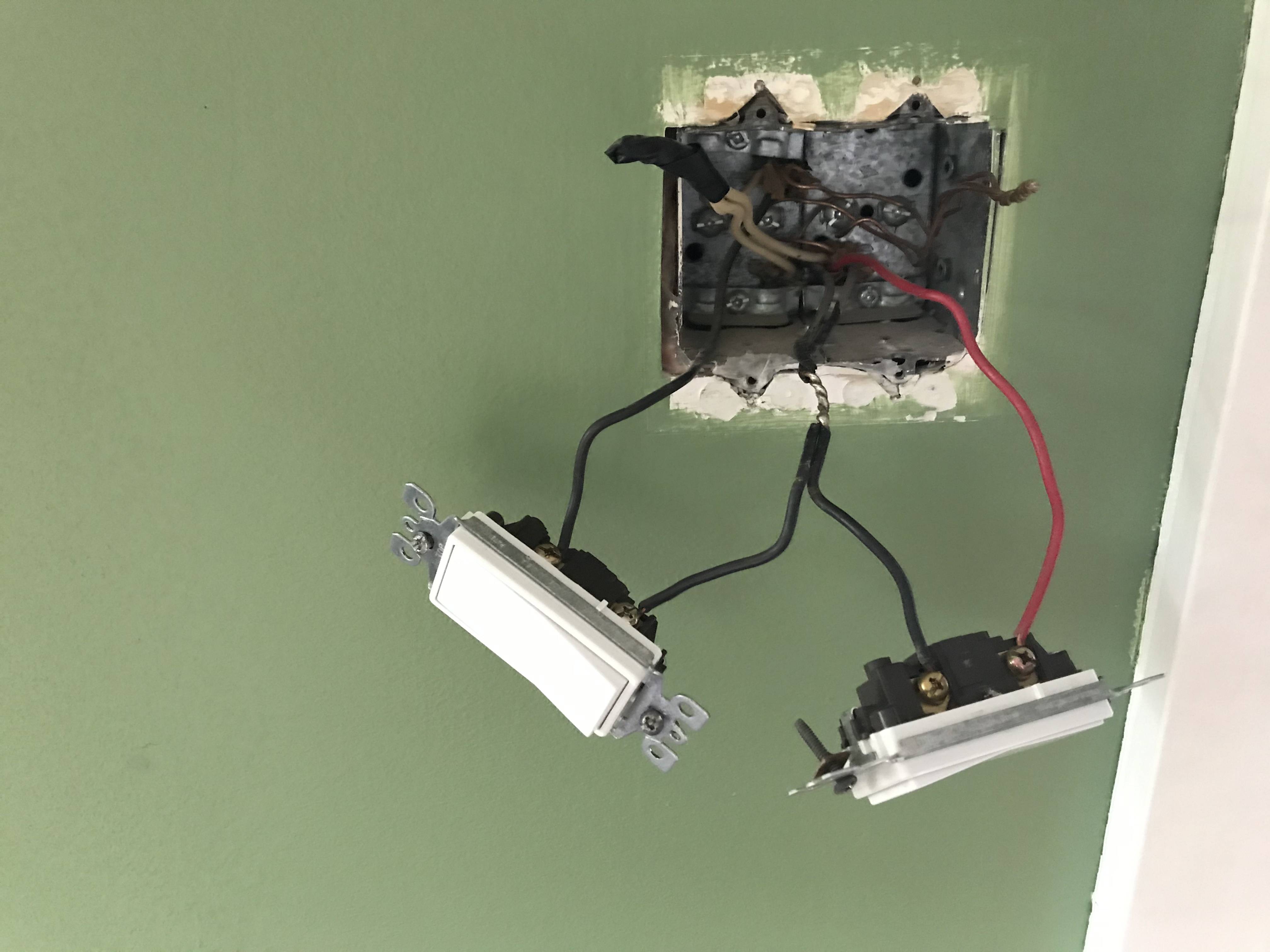
I was investigating a non working switch and found 2 circuits coming into the box. A 12/2 and 12/3. The first switch is serviced by the red and the black crossed wires. THe second switch is serviced by the crossed black wire and a black wire going to 2 lights in series. The neutrals and grounds are pigtailed and travel to the lights also. The first switch controls the light the second switch does not appear to control anything. Is this safe? What would be the purpose of this crossing of hot wires? How do i remedy this unusual configuration? My intent is to be able to control the lights on the separate switches.
-
Can you post photos of the insides of the light fixture boxes in question?– ThreePhaseEelCommented Jun 22, 2020 at 3:33
-
Could the second switch have been provided for future installation of a ceiling fan or similar?– ehbowenCommented Jun 22, 2020 at 8:42
-
Good point. I assumed that the two feeds coming into the box were live. When in fact they may not be.– ShawnCommented Jun 22, 2020 at 12:36
-
You have one feed (in), and two switched hots (out).– EcnerwalCommented Jun 22, 2020 at 12:55
2 Answers
Terminology: "crossed wires" is simply a "pigtail" so that the single hot feed can be used by both switches.
This is utterly normal and safe, done normally. Normally is with a wirenut or similar insulated mechanical splice device - I had at first thought that you'd removed a wirenut for the picture - but my second thought is that they are soldered and the joint is uninsulated, which is not normal or safe, but is easily corrected. Likewise, the neutrals and grounds do not appear to have wirenuts, and this makes me think you may need to buy a large container of wireneuts and to check every electrical box you have for wiring done by whoever installed these switches.
So, the hot feed comes in on the black wire of the 12/3 cable, and the switched hots go out on the red wire of the 12/3 cable and the black wire of the 12/2 cable. Where the 12/2 cable goes we don't know, and evidently you don't either as it "does nothing". That part is utterly normal and safe. When you find out where the 12/2 cable goes, you should be able to switch something with it.
The substandard splices are a concern, and the possibility that many places in your home may have similar substandard splices (you had an amateur in this box, we don't know how far they went in your house) is a concern.
-
-
@JimStewart -- they may be twisted and soldered, but the tape looks to have been omitted Commented Jun 22, 2020 at 11:39
-
I thought the OP might have removed the tape so we could see the splice. Bare sections of hot wires is of course unacceptable. Commented Jun 22, 2020 at 11:45
-
1Yes i removed the tape to see what was underneath, and they were twisted soldered and then taped.– ShawnCommented Jun 22, 2020 at 12:00
-
The soldering we can see looks pretty competent, and mind you soldering big heavy heat-sucking #12 wires without cooking/curling the insulation jacket is no small trick. Whoever did this, did it a lot. Seems like an old-timer at the end of a career. Did not get the memo on modern practices.
That work
You're supposed to insulate wires better than that, though.
Myself, I would layer the X-splice with electrical tape and then also pull the wires off the switches and slide shrink tubing over that and shrink it over. A proper job done with 2 layers of friction tape (tied off) and vinyl tape is far too hard for a novice. Just do the shrink tube thing.
Alternately, cut the X-splice dead center in the soldered area and stick each still-soldered half into a MAC block, which is listed for multiple wires.
The neutrals, I'd shrink-tube that. Vinyl electrical tape is notorious for the adhesive perishing and the tape falling off.
As for what's happening electrically
I want you to get a 5-pack of colored electrical tape, and re-mark the black wire from the top cable blue. Because by sheer luck, the colors of all the other wires correspond to their function (and to the conventionally preferred color codes sometimes used).
White - neutral.
Black - always-hot.
Red - switched-hot #1.
Blue - switched-hot #2.
The lower /2 and /3 cables are supply from the panel, and onward power to other points of use. Don't know which is which, don't care.
The /3 red is for one light, and just the way they wired it, it happens to be on the way from/to somewhere else that needs power for other stuff.
The /2 blue from the top cable is for the other light.

