6

I've installed light switches in other parts of our house, but there is one pair of dimmers that mystifies me. One is a normal dimmer and one is supposed to be a three way dimmer, but the latter is wired incorrectly so that the dimmer and remote switch must be both on at the same time.

There are three bundles of wires coming into the box and I have no idea what is supposed to be wired to what.

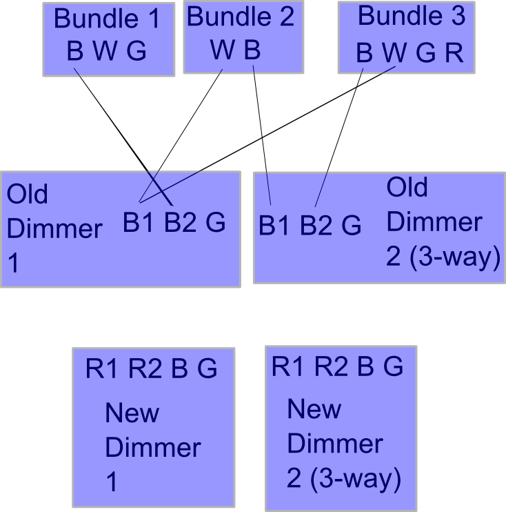
I've drawn up diagram of how they are currently wired.

enter image description here

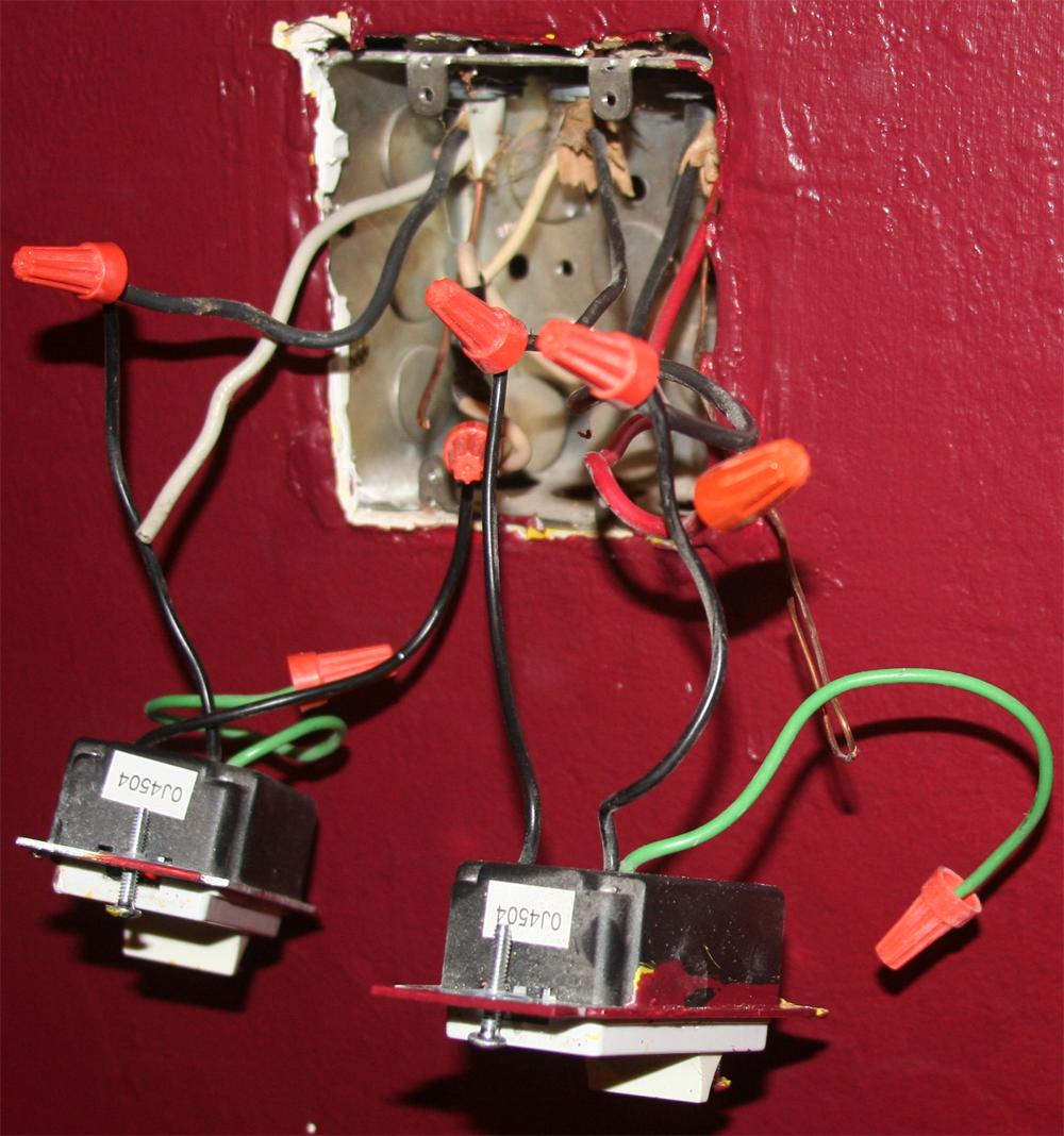
In all other boxes in the house there is one bundle per switch and the wire colors are consistent. In this case there are 3 bundles used for two switches and the whites from two of the bundles are tied together for some reason. I have no idea which wires from the 3 bundles should match up with the wires on the new dimmers.

enter image description here

EDIT 2:

Here are the voltages between the two grounds and every other wire. The things to note are:

  • There is a 17 volt difference between the two grounds.
  • The only live wire appears to be W2 (white from bundle 2). This seems crazy. How did the old dimmer 2 ever work if it wasn't connected to a hot wire?
  • The difference between G1 and W2 is 102, but the difference between G3 and W2 is 47.

VOLTAGES (G1 is ground from bundle 1. W2 is white from bundle 2, etc.):

    G1  G3
G1  0   17
B1  1   21
W1  1   21
B2  1   20
W2  102 47
B3  19  1
W3  18  0
G3  17  0
R3  19  1
5
  • Do both of the switches in the picture control the same light(s)?
    – Tester101
    Commented Oct 31, 2011 at 12:00
  • Can you determine where each of these wires terminates? I'm guessing bundle 3 is to the 3-way switch, but aside from that it's hard to tell where the other bundles go.
    – Tester101
    Commented Oct 31, 2011 at 12:34
  • Was there a lightbulb in fixture 1 when you did that test? The voltage on G3 makes me think there's a short somewhere on that line, so I'd recommend against using it until you can find the cause.
    – BMitch
    Commented Nov 6, 2011 at 1:43
  • Yes there was a lightbulb. If there's a short somewhere I think I will have to just call an electrician to straighten this out. Thanks for your help! I'll print out this page and give it to the electrician so he doesn't need to start from scratch. Commented Nov 6, 2011 at 4:43
  • In this case, you'll probably need to open up all the fixtures, check why there are no hot wires in bundle 1, and figure out where the current is coming from on bundle 3. Unless you're up for a lot of debugging, an electrician is the right call. Good luck.
    – BMitch
    Commented Nov 6, 2011 at 11:51

1 Answer 1

5

White wires are your neutral. You don't switch the neutral, you switch the hot, otherwise, contact with an off fixture could electrocute you if you contact a ground. Therefore, the whites are frequently tied together, with the exception of cases where the white is being used for something else, like a switched wire.

For a 3-way switch, you need an extra wire, which I prefer to use the red wire of a 3 conductor cable. It looks like they've done exactly that in your setup. For more details on how 3 way switches are wired, you can review the various diagrams on this site which include many of the possible wiring variations.

Edit2:

Thanks for the picture. That, a nights sleep, and your description of the other side of the 3 way switch narrow down how this could be wired. I was hoping for the best from your previous electrician, but it looks like you got the worst. Someone really didn't know what they were doing in this J-box. Also, that doesn't appear to be a 3 way switch on the right, at least, not yet, which is why it never worked right. Note, unless it's specially designed to work with 2, you should only have 1 dimmer on a 3 way switch configuration. The other side should be a non-dimming 3 way switch.

Here's my assumption: Bundle 1 goes to fixture 1, Bundle 2 goes to fixture 2, and bundle 3 goes to the other 3 way switch. It looks like all the line wires are in the fixtures themselves (otherwise, you'd have at least one more bundle coming into this J-box).

What I'm not going to assume is that white is actually white in bundles 1 and 2. Most likely it is because of how the current switches are wired, you want to test this to be sure. With the power off and the old switches disconnected, check for continuity between each of the wires in bundles 1 and 2 to ground (use bundle 1's ground for your tests). And with the power temporarily turned on (be careful with exposed live wires), make sure the current only appears between ground and black. If any of the wires are mis-colored, put some tape on the end and label it, and go by the label, not the color, in the below instructions.

Here's what you should do to clean up the mess:

Step 1: Tie all the grounds together, including all 3 bundles and both switches that you replace. Use a short piece of exposed copper to connect the switches if they don't have their own wires. Make sure the wire nut is large enough for all 5 wires. If you can't find a ground on bundle 2, I would double check fixture 2 to make sure it's grounded, and if so, the ground from bundle 1 is all you have to rely on for everything else.

Step 2: Wire up switch 1 like normal, black and white to the two screws on the switch. Nothing connecting the other side is necessary if the above tests worked. If the white from bundle 1 is faulty, connecting to the white in bundle 2 will work, but you really want to find the problem and fix it.

Step 3: Your 3 way switch appears to be variation 1 on the above site, with the line coming to the fixture itself, bundle 2 is the left line in the diagram, and bundle 3 is the right wire in the diagram. The whites from bundle 2 and 3 are tied together and to nothing else (unless a connection to switch 1 is needed). The black from bundle 2 connects to the typically white screw of switch 2. The red and black from bundle 3 connect to the two separate black screws on switch 2, but it doesn't mater which is which at this point. Double check the other end of the 3 way switch to be sure that the white is on the correct screw.

Step 4: Temporarily check your work with the power on. If you don't like the direction of the 3 way switches (I prefer both switches being down as "off"), you can just swap the red and black on either switch to reverse them.

Tip: if the dimmers are large, and the push in connections on the back have an adjustable clamp that closes when you turn the screw, then use the push in connections on the back of the 3 way switch to reduce the risk of a short on the side.

Standard warning: while working with electrical, always have the power off unless you are doing a quick test. Before doing any tests, make sure no wires are shorted with any others. And during any quick tests, make sure you don't touch those wires with anything other than the voltage tester.
7
  • You mention that white wires are neutral, but the right dimmer isn't wired to any white wires. Any idea why bundle 2 even exists? It would seem that black, white, and green/ground from bundle 1 would be enough to wire the left dimmer. The black, white, red, and green/ground would be enough to wire the right dimmer as a 3-way. Why would the left dimmer use black and white while the right dimmer used black and black? Could I use a multimeter to figure out if I can just ignore bundle 2 and wire it like I'd normally expect it to be wired? Commented Oct 31, 2011 at 1:25
  • @HappyEngineer, it's late, and I just reread your first sentence to see that the wiring is indeed incorrect, sorry about that. I got the impression that all of this was in a single junction box, but now I'm not sure that's the case. Can you clarify? Where is the 3rd screw on the 2nd dimmer? And where is the R wire going on the 3rd bundle?
    – BMitch
    Commented Oct 31, 2011 at 2:11
  • Only two wires are connected to each of the dimmers. Presumably that's why the 3-way doesn't work as a 3-way. Neither is grounded. Right now the lights don't turn on unless I slide the dimmer to the top and also turn on the switch in the other room. The R in the 3rd bundle is not connected to anything. If I didn't draw a wire connecting to it then there's nothing connected to it. The white and green from bundle 1 and the red and green from bundle 3 are unconnected. Commented Oct 31, 2011 at 2:37
  • I already replaced the switch on the other side. The other side is wired normally with 4 wires (a red, a black, a white, and a copper ground). Commented Oct 31, 2011 at 2:37
  • That diagram shows what's happening in just one juction box. There are 3 bundles coming in the top and two dimmers wired to those wires. I'll try adding a picture of it. Commented Oct 31, 2011 at 2:40

Your Answer

By clicking “Post Your Answer”, you agree to our terms of service and acknowledge you have read our privacy policy.

Not the answer you're looking for? Browse other questions tagged or ask your own question.