2

I've been thinking of ways to do home automation that is somewhat future proof (hardwired); and the best idea I have is to use relays for lights on a 3 way switch circuit. Put in a dual pole dual throw relay and have it emulate a 4 way switch. Also add a current sensor so I can tell if the light is on or off (secondary goal). All the lighting circuit wiring is in the attic (1 story house) so I'll splice the box in above. Due to the nature of the way a 4 way switch works this should be passive and allow for simple switches to be used unlike what I saw here Any obvious problems with this DIY home automation?. Also means that if the automation logic is removed the switches will work as normal. I can put these in now and worry about hardware/software later; having all control and sensor wires run back to a central location.

Question is what relay do I need to get, and how would I wire it up in order to accomplish this task? I was thinking of using 24vac coils because they are very common (in homes) but that makes it harder to hook up to a logic board as I'll need another relay to convert DC to AC for the coil on the 120v (USA) relay.

Pretty sure I would need a DTDP (or 2x STDP) latching relay but I'm not sure which one to get and how to wire it up so that the circuits cross like X or goes parallel like = when given a switch signal.

Making all switches be 3 way wouldn't be that hard to do in this house; so I could do this for every light switch without too much hassle.

3
  • With a 4-way switch there is no dedicated off position. Which will limit its usefulness in home automation. Commented Jul 25, 2014 at 19:25
  • The advantage of this setup is that it is passive. If the home automation disappears/doesn't work, normal wall switches still work. Usage of a current sensor is how I was thinking of telling the state of the circuit (on/off).
    – mikeytown2
    Commented Jul 25, 2014 at 22:09
  • 1
    Why sense current when you could measure voltage? You could wire an outlet in parallel with the fixture, somewhere in the basement or attic, and use it to drive another relay, that you could unplug to remove later. That relay could then connect to a open/close sending module of the HA brand of your choice. They all have these modules, for use with magnetic reed switch sensors. Or you could connect these relays' controlled contacts to a raspberry pi for the sensing headend. Simpler and more easily removable than a CT anyway. Commented Jan 8, 2016 at 1:06

3 Answers 3

2

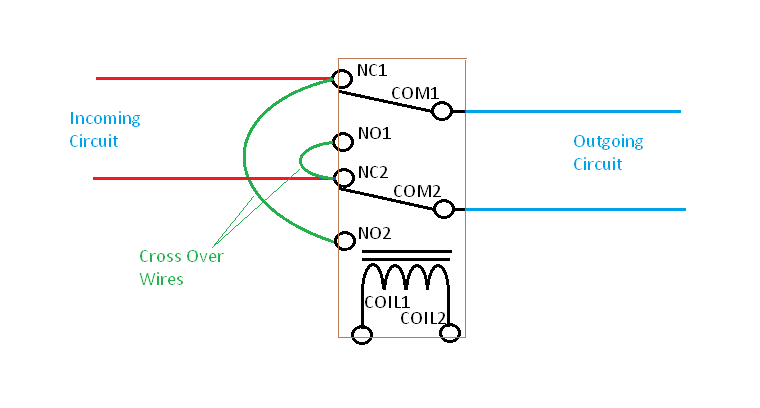
You can purchase and utilize a common DPDT type relay (Double Pole / Double Throw) to create a cross over switch. It is pretty easy to understand from the following relay diagram:

enter image description here

You connect one circuit to the two NC (normally closed) terminals of the relay. The other circuit connects to the two COM (common) terminals. Then you add two additional wires which cross connect the two NC terminals to the opposite NO (normally open) terminals.

The coil of course is driven with the control voltage that you have selected. The simplest control voltage to use would be +12V DC. There are plenty of relays available that have 12V DC coils and your remote automation control can use simple transistors to drive the relay coils.

If you go ahead and use 24V AC for the relay coils then you would have to use an additional relay for each switch control to translate the switching from the AC realm to the low voltage DC realm. (There are circuit components available that can switch the 24VAC but it gets more complex than necessary for an application where +12V DC can be easily used instead. And then you can derive the needed +12V DC from a re-purposed computer power supply.

A major concern when building any type of system such as this, where you bring remote control wiring into the mains wiring boxes of your house, is safety and isolation. Only relays rated properly should be used and you would bear the safety liability associated with stringing the control wires around your house.

2
0

Personally, I'd stick with a carrier-current or radio system -- TREMENDOUSLY easier to install, lower risk due to the inherent isolation, UL or equivalent certification so you aren't going to have home inspectors failing your place for code violations... and, frankly, if you are asking this question you shouldn't be designing this system.

1
  • 1
    The Functional Devices relays linked in the comments on Michael Karas' answer are UL listed... Commented Apr 3, 2015 at 16:29
0

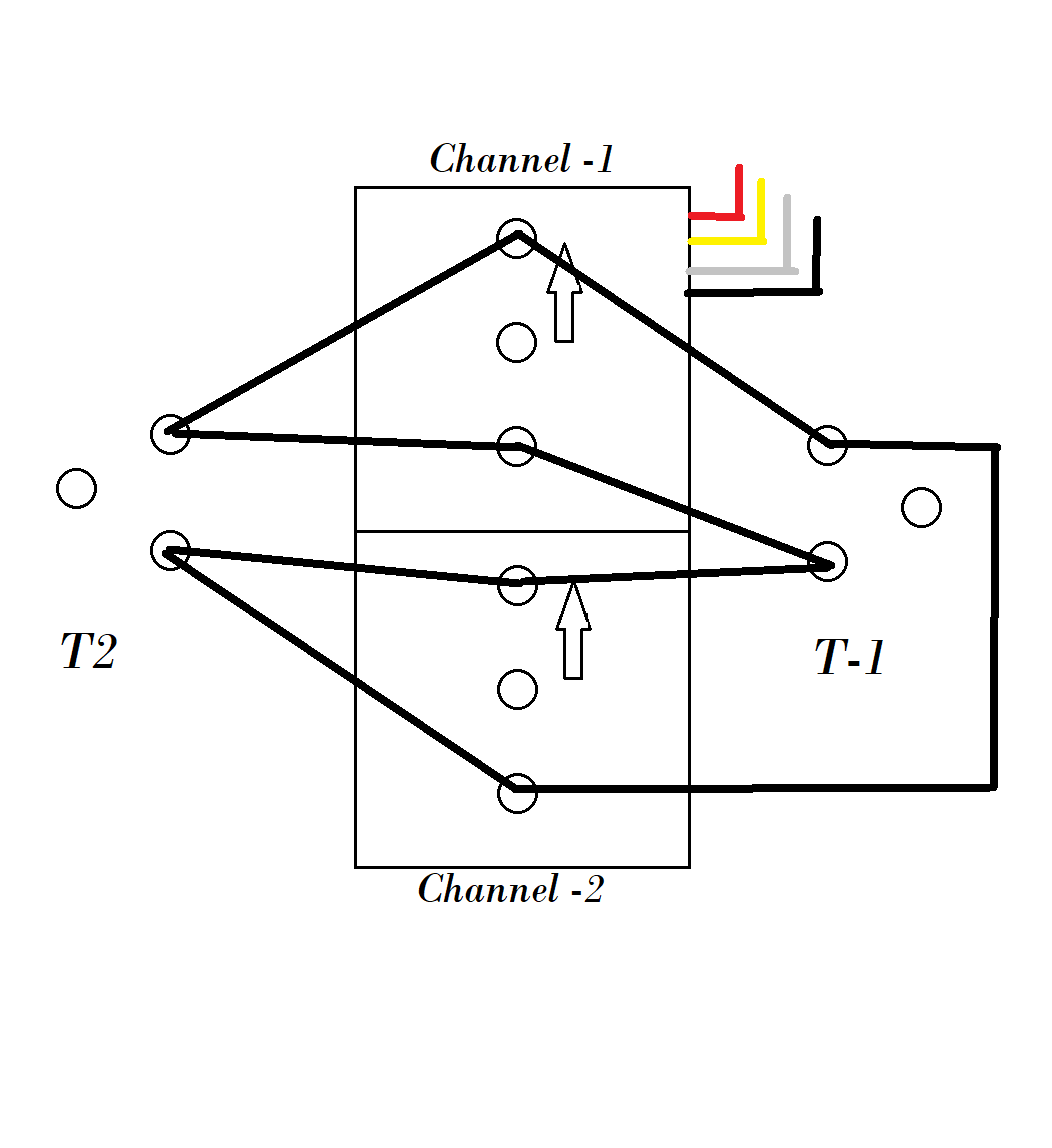
Just follow like the imageIf you already have a fully functional relay module with a minimum of 2 channels than you can emulate this type of circuit by wiring it this way...I am sorry for not being able to make a slide for this...so m uploading an image of the hand drawn circuit...I have personally done this at my house... You have to switch both the relays

Your Answer

By clicking “Post Your Answer”, you agree to our terms of service and acknowledge you have read our privacy policy.

Not the answer you're looking for? Browse other questions tagged or ask your own question.