1

I am looking to install a geothermal heating system to provide hot water and heating in a small home. I am aware that constant cycling of the geothermal heat pump is not desirable, so it is usual to use a buffer vessel to store residual heat for the heating loop. The problem is that we are very constrained on space. We also intend to use the heat pump to provide hot water.

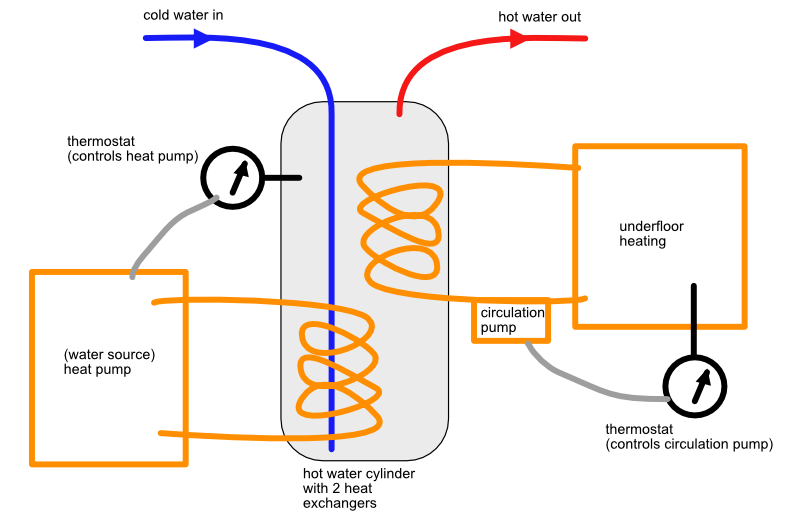
I have found some hot water cylinders that have dual heat exchangers. These are often used when you have multiple heat sources, but I was thinking that there is no reason i could use one of the exchangers as a sink instead of a source, and use it to heat the underfloor heating loop. Then the hot water itself is used as the buffer to reduce cycling.

The hot water cylinder thermostat that would be used to control the geothermal heat pump, aiming to keep the hot water at a sufficiently high temperature. The room thermostat would control the circulation pump on the underfloor heating loop.

Please see the attached diagram (I have ignored expansion vessels, etc, for simplification):

enter image description here

Logically, this seems like a sound solution to me: it avoids the need for a dedicated buffer tank, reduces the cycling of the geothermal pump, and eliminates the need for complicated valve controllers to efficiently balance the distribution of heat between hot water and heating.

Am I missing anything obvious? What are the caveats to a solution like this? Any advice appreciated.

8
  • First I would allow the cold to enter at the bottom - it disturbs the stratification less.
    – Solar Mike
    Commented Mar 9, 2020 at 11:30
  • Thanks @SolarMike - this is just an example diagram. The inlet position would be as provided on the (commercial) tank.
    – Matt
    Commented Mar 9, 2020 at 11:32
  • Well provide a diagram without basic errors so we know what you do and don’t understand.
    – Solar Mike
    Commented Mar 9, 2020 at 11:38
  • resized the image and now its uploading - added a dip tube for you.
    – Matt
    Commented Mar 9, 2020 at 12:00
  • 1
    @OldUncleHo Propylene Glycol on geothermal loop (both sides) and the underfloor heating loop. The hot water in the tank acts as a buffer, and is used to supply domestic hot water (which comes from potable cold water supply). Geothermal loop will be up to 60 degrees, so hot water cylinder will cap at around that. Underfloor heating pump thermostat will be capped to ~50 degrees intake temp to preserve flooring condition.
    – Matt
    Commented Mar 9, 2020 at 13:46

2 Answers 2

1

There's an easier way to do this

Your first issue is that you are using the domestic hot water as your buffering medium, which forces several constraints on your original proposal, including the need for two heat exchangers connected in series, as well as having to keep the tank at or above 135-140°F to keep your tank from turning into a Legionella nest. Furthermore, the two-exchanger configuration would require two feedwater trains, two air separators/air vents, and two expansion tanks, which adds needless cost and complexity.

Instead, I would use a reverse indirect hot water heater such as a Turbomax or Ergomax as the buffer tank. This uses the boiler (heat pump) medium as the buffering medium, running the domestic water through a heat exchanger coil in the tank; thus, you effectively get tankless performance without many of the tankless drawbacks. It also provides a convenient hydraulic separation point between the heat pump and the load, and helps separate that ever-present pest known as air from the water in your heat pump system.

On one side, you'd have your heat pump and its associated circulator, controlled by the tank aquastat in order to keep the tank at an appropriate temperature, with the supply and return lines connected to tappings on the tank. On the other side, you'd have your radiant loop, connected as a mixing loop with its own circulator and a mixing valve in the supply side, mixing return water with supply water to feed the circulator suction.

Unfortunately, there's no clear place to put the water feed and expansion tank in this system, because of the apparently-packaged nature of the heat pump/circulator combination; if its circulator is indeed external, then I would put the expansion tank and such immediately on the suction side of the heat pump circulator. Also, don't forget to put a suitable backflow preventer on the water feed to this all, especially since you're planning to use glycol in this loop.

And yes, having a hydronic professional work with you on this system design would be a good idea; all I can do is give you a starting point for this, but they'll be able to figure out pesky things like where to put the expansion tank much better than I can, as well as being familiar with local backflow prevention requirements and such.

So, you want to add more heat sources to this?

Fortunately, because we have the reverse-indirect/buffer supplying hydraulic separation in our system, we can add other heat sources to this system, even "wild" ones, quite simply, without the need for extra heat exchangers and their associated complexities. This is done by manifolding the supplies and returns of the heat source loops together at the tank, or by using additional tank tappings if they are available, for that matter. Each heat source has its own circulator and flow-check/non-return valve; the main complexity is in the control logic to decide which source(s) should supply heat when the reverse-indirect's aquastat calls for it.

If you want more information than I can give in a Stack post, by the way, I would recommend John Siegenthaler's articles (which are largely collected into a set of 5 e-books), as well as Dan Holohan's "Pumping Away", and Caleffi's idronics series of design journals.

2
  • Thank you - I hadn't come across such a buffer from local geothermal providers. I have now sourced one directly from the manufacturer (cordovari), with a couple of additional heat exchangers to allow me to use solid fuel and solar thermal to augment the geothermal. Many thanks - this is exactly what I intended to achieve.
    – Matt
    Commented Mar 10, 2020 at 6:13
  • 1
    @Matt -- you don't need extra heat exchangers in the tank for the extra heat sources, either! You can simply plumb them in parallel on a manifold going into the tank, or on separate tank tappings for that matter, if you can get your tank setup that way that is. Isn't hydraulic separation wonderful? Commented Mar 10, 2020 at 22:02
0

Depending upon how sophisticated you want to get, I see a number of potential issues. Sizing of everything is very important. This should be engineered.

Here are some of the potential issues: the heat pump might not be able to supply enough heat during high demand periods like very cold outside and ppl taking showers.

The supply temp to the floor is unregulated. You don't want to heat up the floor a lot when it's mild outside or you'll get a lot of "overshoot" of the tstat setpoint, which wastes energy and can be uncomfortable. Most hydronic heating systems have an outdoor temp sensor that regulates the supply temp to the floors. At a minimum, I'd put a mixing valve on your floor supply between the supply to the floor and the return.

You should get an intelligent tstat that can learn about the performance capacity of the system and adjust to it. IE: Adaptive Intelligent recovery.

This will be a substantial investment for you and my recommendation is to have a designer/engineer help with the planning and sizing. I hate to post "call a pro" here, but unless others here are willing to provide a lot of help, it's probably worth it.

5
  • The solution will be sized accordingly. I mentioned in another comment, but the flooring intake will be capped at ~50 degrees. The thermostat in the diagram is to ensure minimum interior temperature. Im not accounting for exterior temperature at all, but thats certainly something to consider at a later stage. Im not concerned about the sizing, etc - i just want to know if there is anything obviously wrong with using the DHW as the buffer instead of using a buffer tank.
    – Matt
    Commented Mar 9, 2020 at 15:53
  • Will your floor heat tubing be in concrete? or other means of radiation? If in concrete, that is a large thermal mass subject to overshoot if supply temp is too high. If using a finned style hydronic, less prone. Commented Mar 9, 2020 at 16:07
  • It will be embedded in concrete. The supply will be capped to ~50 degrees on intake. I haven't heard of finned-style - could you point me at a link please? I cant find anything while googling.
    – Matt
    Commented Mar 9, 2020 at 16:20
  • Thanks for the comment on the mixer. Thats a nice idea using the return. I completely misunderstood the first time.
    – Matt
    Commented Mar 9, 2020 at 16:32
  • 1
    Here is a link. hopefully it works. if not search for "plate type radiant heating" s3.amazonaws.com/finehomebuilding.s3.tauntoncloud.com/app/… Commented Mar 9, 2020 at 16:47

Your Answer

By clicking “Post Your Answer”, you agree to our terms of service and acknowledge you have read our privacy policy.

Not the answer you're looking for? Browse other questions tagged or ask your own question.