If your HVAC situation permits it...
The ability to have a source of heat that works during a power outage is a massive asset, especially if power outages are a serious concern (as they typically are on the long overhead feeds found in rural areas). Either a wall furnace (Empire-style) or a gas fireplace can be used; either way, you'll want a sealed combustion version that draws its combustion air from a dedicated outdoor source to avoid any potential issues with backdrafting, CO, and the likes.
Dealing with the original problem, though
However, not all folk are in a position to have heat that works during a power outage, either due to a lack of fuel (gas) service to their location, or due to limitations of their existing HVAC systems. Given this and a couple of assumptions about your well pump, namely that it is a single-phase, 230V unit of 2HP or less and uses a 2-wire start system with a direct-operating pressure switch control, we can solve this problem quite simply and relatively cheaply (under $100) with a few fairly basic industrial-control type parts:
- A 230VAC, 20A, DPDT enclosed relay, namely the RIB02P (this is basically a lightswitch that's rigged to an electromagnet so that it can be controlled by an electrical signal)
- A 22mm, 1NO/1NC, momentary-contact illuminated pushbutton with a 230VAC illuminator, in a color of your choice
- And a single-hole 22mm control station enclosure (metal or plastic, rated to go where you're putting this at) with a couple of 1/2" KOs in it.
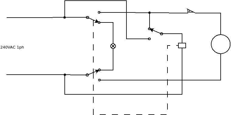
This all gets wired up as follows, or as per the diagram below (which omits grounds for clarity's sake), once you attach the box to a suitable wall surface (note that most control station enclosures don't support being flush-mounted inside a wall in a finished space, as they're designed for industrial use), mount the relay to one of the 1/2" KOs using a locknut, fit the switch through the hole in the front of the box, and feed the incoming and outgoing cables through the remaining knockout(s) using cable clamps:
- One of the incoming hot wires connects to a normally open (NO) terminal on the pushbutton along with one of the common (COM) wires (yellow or purple) from the relay
- The other incoming hot wire connects to a coil (brown/white) wire and the other COM wire from the relay
- The NC wires (blue and grey) from the relay connect to the lamp terminals on the illuminated pushbutton
- The NO wire (orange or brown) from the relay that corresponds to the COM wire you picked to connect to the incoming hot going to the pushbutton connects to a normally closed (NC) terminal on the pushbutton, along with one of the wires going onward to the pressure switch and well pump
- The other wire going to the well pump/pressure switch connects to the other NO wire from the relay
- The other coil wire from the relay connects to the remaining NO terminal on the pushbutton, which then jumps to the remaining NC terminal on the pushbutton with a short length of insulated wire
- Last but not least, the incoming and outgoing grounds connect to each other (and to a ground pigtail, if the box you used is metal)

This all forms what is known as a stick circuit, using the relay to provide a memory of power failure in the following fashion:
- We start with the power off. The pushbutton and relay contacts are all in their Normally Closed positions, which means that the relay coil has one side connected to the power that's being switched by the relay's Normally Open contacts, and the incoming power is connected to the indicator, not to the rest of the circuit.
- When we apply power to the circuit, the indicator lights, as it's connected to the incoming hot through the relay's Normally Closed contacts. Nothing else happens, though, since the relay's coil is not powered.
- Pushing the button switches the switched side of the relay coil from being connected to a Normally Open contact of the relay (connected through the button's Normally Closed contact) to being powered directly from the line through the button's Normally Open contact.
- This pulls in the relay, energizing the pressure switch and pump motor through both sets of Normally Open contacts on the relay while de-energizing the Normally Closed contacts, which causes the indicator to go out. (Why both sets? It's because both sides are "hot", and the appropriate motor rating for the power relay used requires all poles to be switched.)
- Releasing the button at this point connects the relay coil to the now-powered Normally Open side of its own contacts through the button's Normally Closed contact, thus holding, or "sticking", the relay in its energized position.
- With the button released and the relay energized, the pump can now run normally, as if our circuit wasn't there, while our circuit is ready to detect the next power failure.
- Turning the power to all this back off de-energizes the relay, which causes its contacts to return to their Normally Closed state, bringing us back to the state we were in at the beginning of this description.

