1

I would like to connect a new chandelier to the ceiling of my bedroom. The ceiling box has two cables:

  1. black, white, ground - none of these is hot
  2. black, white, red, ground - black on this cable is hot (120 V to ground)

The hot on cable 2 is not controlled from any wall switch (it seems as if it used to have a ceiling fan/light before). It is hot all the time; each switch checked in the house-none controls the power on this hot cable in the ceiling box.

OK, now there is also a wall switch in the same room that seem to be dead. It has three cables (each has black, white, and ground) and none of them is powered.

  1. black, white, ground - none of these is hot (entering the switch box from the above)
  2. black, white, ground - none of these is hot (entering the switch box from the above)
  3. black, white, ground - none of these is hot (entering the switch box from the below)

Cable 3 in the wall switch seems to be the same as cable 1 in the ceiling box (checked the resistance - 0.5 ohm on 1 and 3 probed, and 0.5 ohm when white on 1 and 3 probed)

I am wondering if I can utilize this dead wall switch to control the ceiling box power (and my new chandelier) without laying out additional cables inside the walls.

For example, I was thinking about using white (neutral) on cable 1 to bring hot to the wall switch (connect hot on cable 2 and white on cable 1) which would bring the hot down to the wall switch through 1-3, connect to the switch, and then bring the hot back to the ceiling box through the same cable 1/3). Then I would use black from 1 and white from 2 to power the chandelier.

Possible or is there any other more "professional" solution?

2
  • 1
    feetwet's answer is the most likely scenario, but I'm a bit worried about cable #2- it's 14/3 or 12/3, but only the black is hot? What is the red wire doing? Is this a relatively new house? I believe the NEC now requires an extra conductor for all lighting circuits, or maybe the red wire is for signal to interconnected smoke detectors. If this is an old house, I can't think of another reason to have an unpowered red wire sitting there, unless the cable is fed from a different switch box that was intended to have 2 switches for light+fan, but they were relocated to the current box...
    – nstenz
    Commented Sep 13, 2014 at 23:54
  • @nstenz: Good call. We need to know how old the house is. (Given all the spare wires floating around I assume it's somewhat old.) The red could indicate the wire is part of a smoke detector interconnect, which will give you very confusing behavior!
    – feetwet
    Commented Sep 14, 2014 at 3:16

1 Answer 1

3

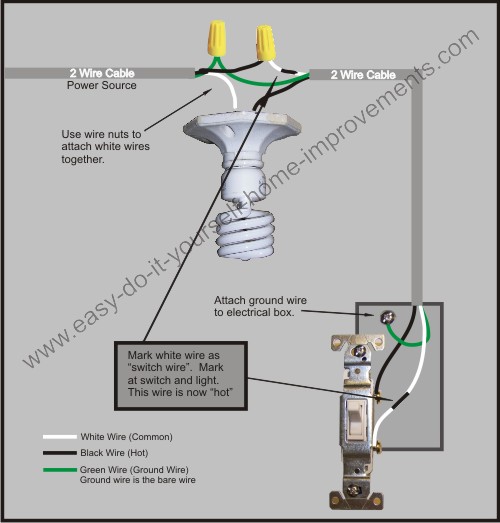
The core of your question is a standard wiring scenario: You have the hot coming through the load and the switch at the end. Your proposed wiring is correct. Diagrams are easy to find online, e.g.,

enter image description here

Of course you should be wary of cables (4) and (5): If they are properly terminated in the work box you can leave them. If they are wired into the switch right now you should disconnect them until you find something else in the house that is not receiving power but should, and then remember that you now have a hot in that junction box you can tap.

5
  • Thanks a lot for the schematic, it confirms what I want to do. I tried to implement this and encountered a different problem. When I connected hot black from (2) to white from (1) (in the schematics above, that would be alternating black-white color), I expected to see 120 V to ground at the end of alternating black-white cable (at the switch). However, I measured around 40 V. I had to mention that there was a short somewhere in the circuit that kicked out the circuit breaker before I measured this voltage.I had to reset the breaker and then measured 40 V.
    – user25202
    Commented Sep 14, 2014 at 2:05
  • Why do I see 40 V only? Am I missing something? It is just the piece of cable that was supposed to bring 120 V from the ceiling box down to the wall switch box.
    – user25202
    Commented Sep 14, 2014 at 2:05
  • That's really bad news: Presumably you have something in the circuit downstream of the last point you can measure 120V to ground that is introducing a lot of resistance. Like an intermittent short or other fire hazard. I would isolate each downstream segment and measure the voltage to ground point to point as I connect the wires along the circuit, and replace the first segment, device, or connection that shows a voltage drop. Cover any exposed conductors like the screw terminals on switches with electric tape. Also make sure all wires meet minimum gauge spec (e.g. 14 gauge for 15 amp).
    – feetwet
    Commented Sep 14, 2014 at 3:09
  • Problem solved. Chandlier working. It was a simple problem, broken copper wire. Thanks for the help.
    – user25202
    Commented Sep 14, 2014 at 4:23
  • Glad you found the break in the wire! To keep the site orderly please either mark your question answered (ideally) or else close it. Otherwise it will continue to show up in the unanswered question list.
    – feetwet
    Commented Sep 14, 2014 at 14:38

Your Answer

By clicking “Post Your Answer”, you agree to our terms of service and acknowledge you have read our privacy policy.

Not the answer you're looking for? Browse other questions tagged or ask your own question.