2

So, I purchased two new Kasa light switches to replace two standard switches in a 3-gang box and encountered a lot more than I was expecting. Almost every wire looks to be black, which is not what I expected at all. I feel moderately handy and have swapped out several other switches and outlets in the house, but this one is really stumping me.

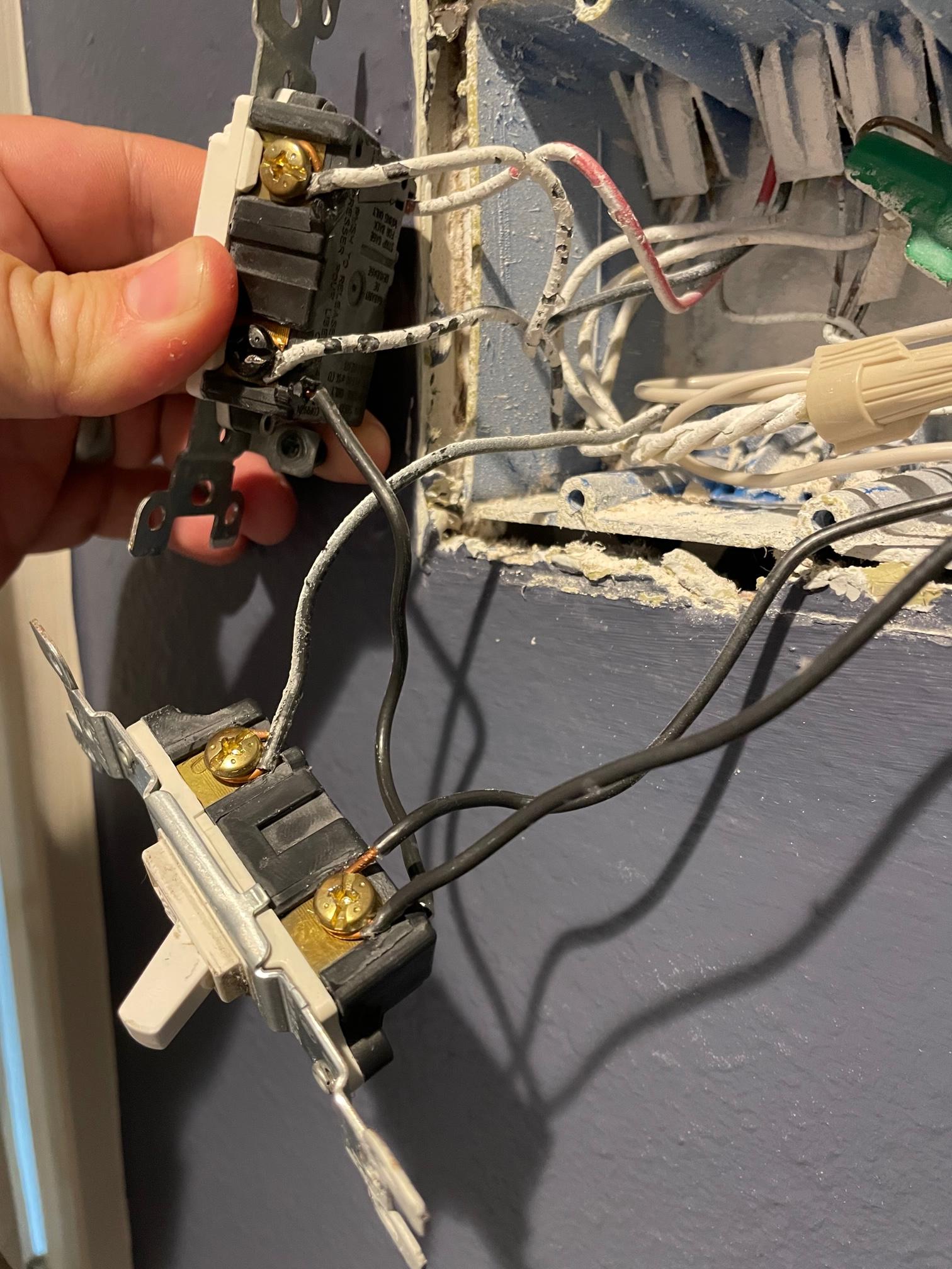
far left light switch

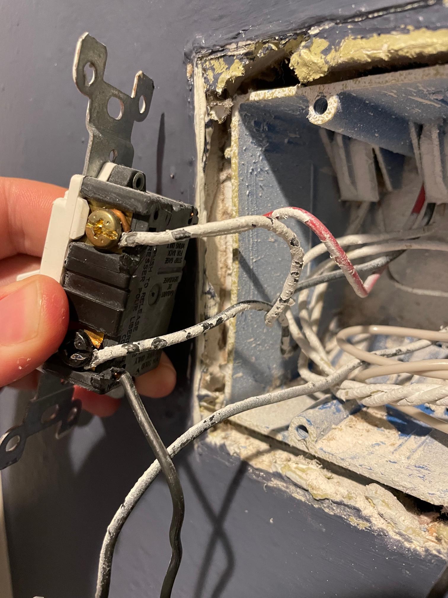
The far left switch has a red wire on the top left (I'm assuming it's going back to the wall since it's definitely a three way), then a wire coming from the wall into the top right screw, then another one from the wall going to the bottom right screw. I have no idea what either of those two screwed wires are (load vs. line).

middle light switch

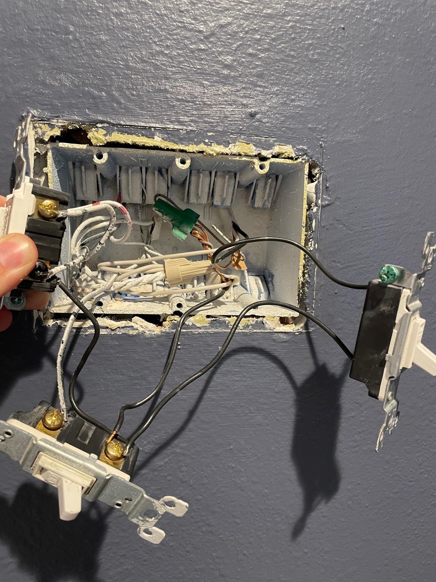
Where it gets fun is that there's ANOTHER wire plugged into the back of the switch that leads into the back of the second switch, with a wire screwed into the top right coming to/going from the wall, and another wire screwed into the bottom right to/from the wall – but THAT wire loops around said screw before plugging into the bottom of the third switch. There is also a wire coming out of the top on the back of the switch that goes to/from the wall.

far right light switch

Taking a step back, this is kind of a mess (to me – this may be normal for electricians!)

all three switches

enter image description here

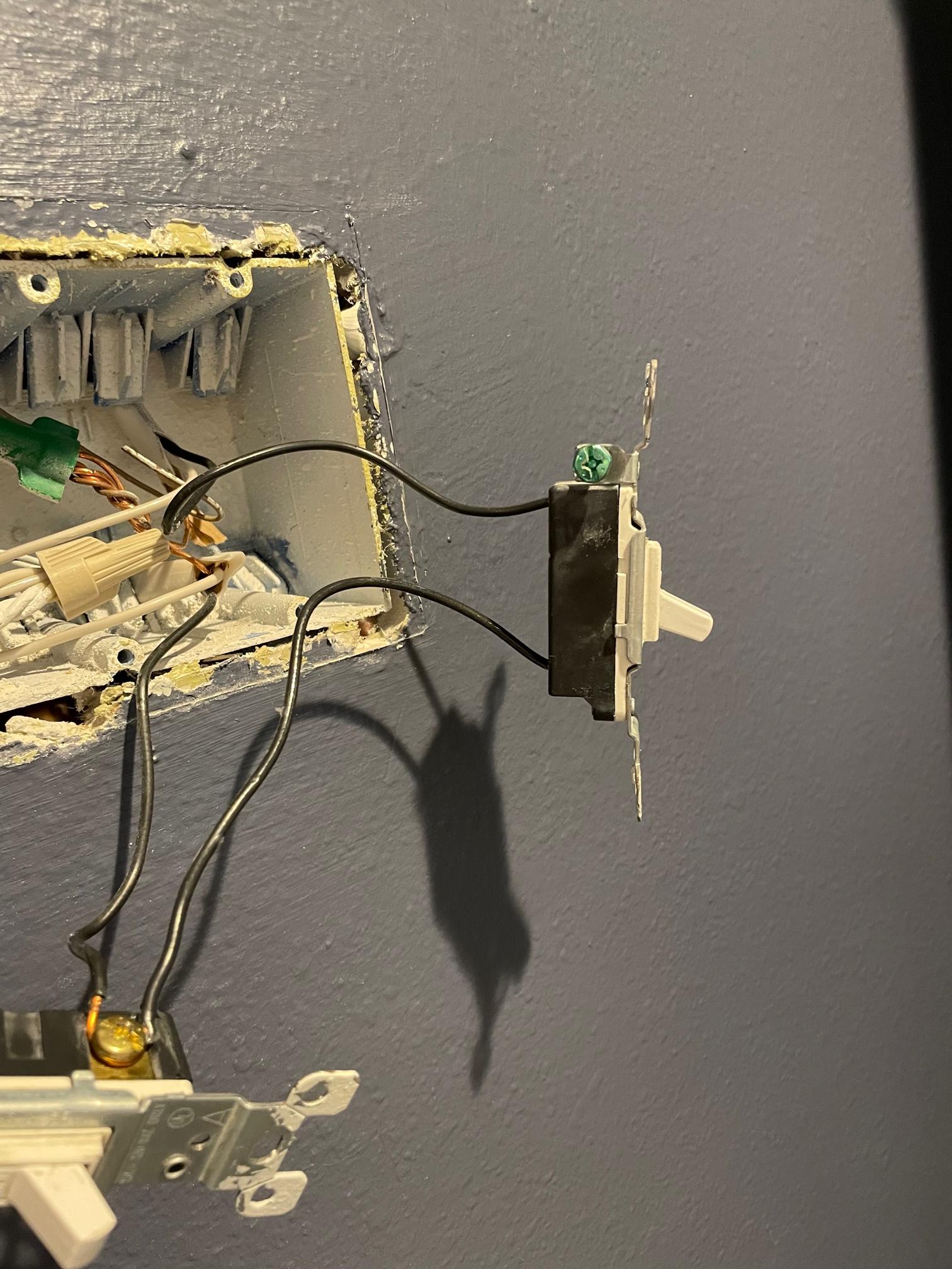
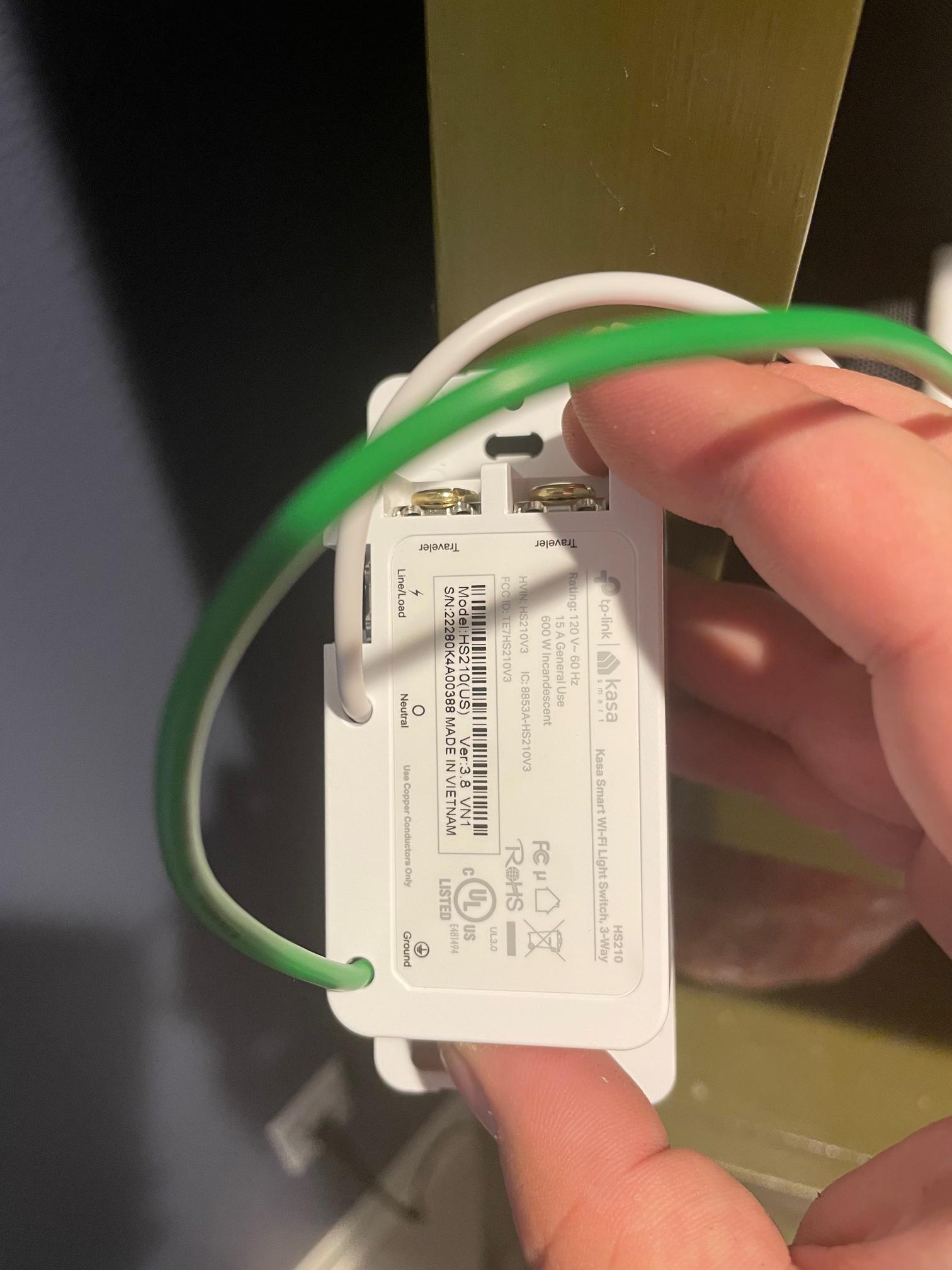
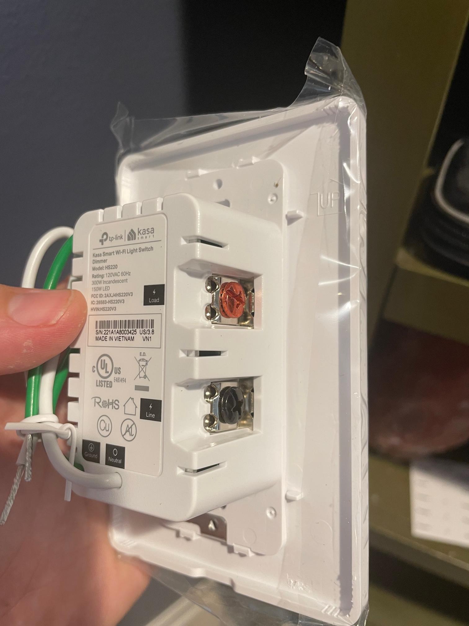
So, where it really gets fun is that I'm trying to figure out what goes where in the back of these Kasa switches. One is a three way (replacing the middle switch which I know isn't a three way switch) and the other is a dimming switch (replacing the far right switch).

three-way switch, replacing middle switch

dimmer switch, replacing far right switch

So, as of now, I feel pretty stuck. I'm going to put all three back in their places and turn power back on, but wow.

11
  • Looks like you've got some problematic wiring issues there. "Back stab" connections where a wire is just pushed in to be held by a thin sliver of metal inside, and multiple wires held by the same screw. Stick with a single wire per screw, and no "back stabs". You may have to buy better-quality switches. The Kasa "2 wires under a plate held down by a single screw" is OK for 2 wires but not optimal. Better to use a single "pigtail" wire to connect to a screw terminal, and attach multiple wires to the other end with a wire nut.
    – Armand
    Commented Jun 12, 2023 at 23:39
  • 2
    @Armand It does look like the two wires is actually one wire with some bare wire loop around the screw, which is okay.
    – crip659
    Commented Jun 13, 2023 at 0:34
  • 2
    I recommend you read an introductory book or find a good online introduction or video tutorial about home wiring. From your description of the wires in your box, it seems there are some VERY basic fundamentals you don't have. You should understand what a "circuit" is, you should be able to draw one with a switch and a light bulb, and understand the function of every wire regardless of what color it happens to be. Your existing switches were wired with some simple tricks that work for them but not for your new ones. This should not throw you off ... if you understand what each wire is for.
    – jay613
    Commented Jun 13, 2023 at 0:39
  • @Armand – there aren't any screws with multiple wires. I think I know what to do, based on the comments below. I think I can take the "stab" wire from the back of the left switch and use that as the load on the middle switch. Then, the wire that loops around that bottom screw on the middle switch can become the load for the far right switch. From there, the top wires from the middle and right switches are their respective lines. I think that would do it.
    – 3mw
    Commented Jun 13, 2023 at 0:44
  • 1
    @3mw Probably a "wire nut" instead. :) To learn how to properly attach a wire nut and the terminology in general is why we are strongly suggesting you get an intro to home wiring book and read it first.
    – Armand
    Commented Jun 14, 2023 at 4:31

2 Answers 2

2

Where it gets fun is that there's ANOTHER wire plugged into the back of the switch that leads into the back of the second switch, with a wire screwed into the top right coming to/going from the wall, and another wire screwed into the bottom right to/from the wall – but THAT wire loops around said screw before plugging into the bottom of the third switch.

Which makes it about 99.9% certain (and the fact that it's the black screw on the 3 way, which you don't think is worth mentioning or noticing supports that) that it's the power from the panel (line) to all 3 of these switches. The wire from the wall is the actual line to the panel, but the wire leading to the other switches carries "unswitched hot" or "line" to the other two switches. OK, and on to some other location since there are two wires into the wall from this word salad, so it could be that the actual feed is the other one of the two - it doesn't matter which. They are all joined together, so they are all "unswitched hot" or "line."

Therefore the other wires connected to the other terminals of the switches are the two travelers on the 3-way, and the switched hots on the regular switches.

Quite logical and straightforward.

When using a 3-way as a regular switch, you connect to the black (or "different colored") screw and ONE of the two brass (or "same colored") screws, leaving the other disconnected. If you don't like the direction the switch is when it's "on" swap that wire from the one brass screw to the other brass screw.

5
  • Very unskilled, but I think I'm following: Yes, bottom right screw on the left switch is black – I didn't catch that. You're saying that wire is hot, top left & right are terminals. That adds up. You're saying the wire in back of left switch feeds power to back of middle switch? In that middle switch, that would make the top right the line? Where I'm confused is the wire that loops around the bottom right screw on middle switch. One end comes in/out of wall, then loops around the bottom right screw, then plugs into the back of the right switch. You're saying that's power?
    – 3mw
    Commented Jun 13, 2023 at 0:25
  • I think I know what to do, based on this explanation. I think I can take the "stab" wire from the back of the left switch and use that as the load on the middle switch. Then, the wire that loops around that bottom screw on the middle switch can become the load for the far right switch. From there, the top wires from the middle and right switches are their respective lines, if I'm following correctly. The last detail is neutral and ground, which it looks like I have neither of accessible here.
    – 3mw
    Commented Jun 13, 2023 at 0:48
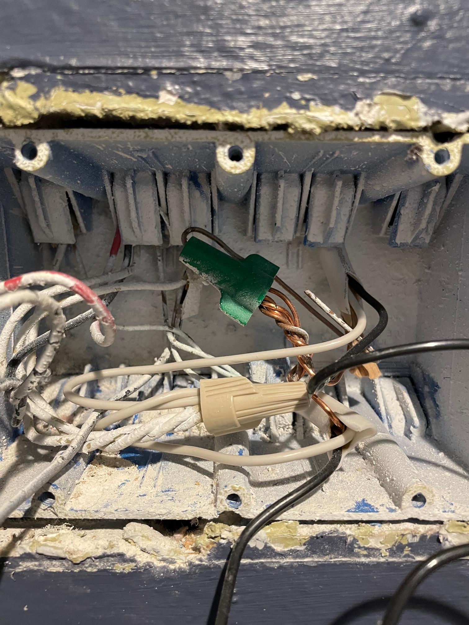
  • Your picture shows that the back wire and the "looped" wire are connected to the same point on the "middle" switch - one from the backstab, one from the screw. that terminal is the line, or unswitched hot, in this case, and in your pictures it's "lower" not "upper" so your words and pictures disagree, and I'll believe the pictures. And you have a bundle of neutrals and a bundle of grounds staring you in the face. At which point one does have to wonder if you are out of your depth more than you should be...
    – Ecnerwal
    Commented Jun 13, 2023 at 1:00
  • Yes, I am 99% out of my depths – this has been much easier in other areas of my house, so I figured this would be the same. I thought I could swap a few terminals and call it a day, and that does not seem to be the case here. I assumed the top terminals for the middle and right switches were lines because they are the only two wires coming in/out of the wall that aren't shared between them, but it sounds like I'm not correct. Also, I saw neutral & ground bundles, but I don't know why the current switches weren't wired to utilize them (I definitely didn't wire this up). Time to make a call.
    – 3mw
    Commented Jun 13, 2023 at 1:19
  • And I just realized I've been using line and load in the wrong direction
    – 3mw
    Commented Jun 13, 2023 at 2:01
3

I've completed the project – here's what I was able to determine: The power started with the left switch and daisy chained to the other two, and eventually into two outlets. Line was at the bottom of each switch, load at the top.

I pigtailed the power to all 4 destinations, connected the proper load lines, neutral, and ground wires. Everything works as expected.

Thanks to everyone's feedback, you changed my viewpoint on the inner workings of wiring and I feel like this was a good growth project.

1
  • Congrats on your success. Please take the tour so you know how to resolve your post.
    – isherwood
    Commented Jun 13, 2023 at 13:11

Your Answer

By clicking “Post Your Answer”, you agree to our terms of service and acknowledge you have read our privacy policy.

Not the answer you're looking for? Browse other questions tagged or ask your own question.