Buss is a fuse manufacturer. A bus is a set of like things.
Link
isherwood
  • 148.7k
  • 8
  • 179
  • 439

Seeking advice on how to rearrange existing breakers and add 2 circuits, including a 20A GFCI/AFCI breaker in a split-bussbus GE panel

deleted 2 characters in body
Source Link
isherwood
  • 148.7k
  • 8
  • 179
  • 439

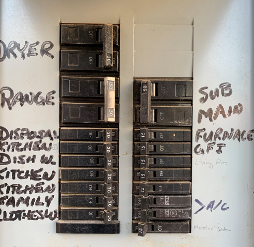
My panel is a GE TX1612RH split-bussbus 125A panel (photo below). It is an outdoor panel, vintage 1980 when home was built. I want to run two 20A circuits to a shed 60-ft away and would like to know if the following changes are advisable and in accordance with Code: 1) Move the 2-pole 30A (thin) breaker for A/C to the slot immediately above the 50A "Sub-Main" breaker, thereby consolidating all 240V loads in upper portion (I think the A/C contractor goofed on the electrical portion); 2) Install a 20A "thin" breaker in lower-left slot for a dedicated circuit for an in-wall 120V shed heater (blank-face GFCI will be upstream of in-wall heater); and 3) Install a "full-width" 20A GFCI/AFCI breaker for everything else in the shed, using the slots formerly used by the 2-pole 30A breaker. Regarding #1: Is it OK to use "thin" breakers in the upper bussbus, or should I replace the 30A thin breakers with the full-width variety. Many thanks!

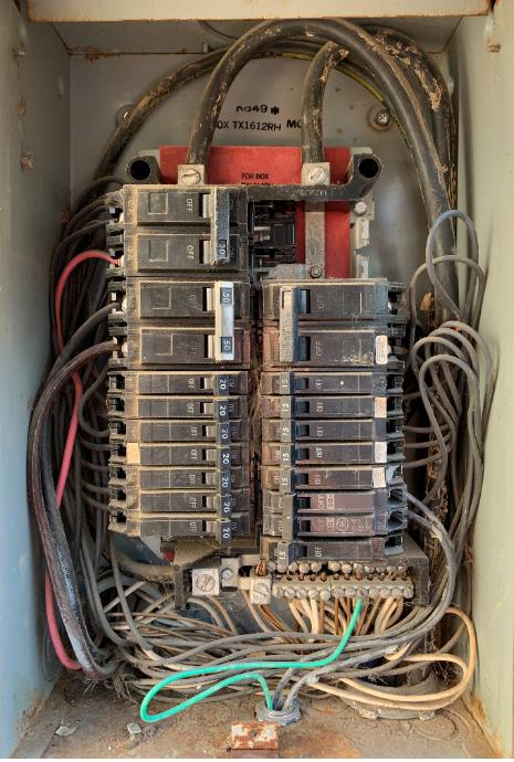
Update #1: Photo of panel interior has been added. Unfortunately, there are no placards or labels on inside of panel door or on back side of cover, so I'm driving "blind." Googling the "K849 *" reference (top of back of panel), I found nothing.

Update #2: The A/C contractor (in 2008) used very MINIMAL wire to reach the 2-pole compact 30A breaker -- not enough wire to extend to the new and proper position of a full-width 2-pole 30A breaker above the existing 2-pole 50A breaker. Any suggestions for a remedying this dilemma? Rules for using red-head connectors wrapped in rubber and vinyl electrical tape? Or must I pull a new run of #10 copper conductors?

enter image description here

enter image description here

My panel is a GE TX1612RH split-buss 125A panel (photo below). It is an outdoor panel, vintage 1980 when home was built. I want to run two 20A circuits to a shed 60-ft away and would like to know if the following changes are advisable and in accordance with Code: 1) Move the 2-pole 30A (thin) breaker for A/C to the slot immediately above the 50A "Sub-Main" breaker, thereby consolidating all 240V loads in upper portion (I think the A/C contractor goofed on the electrical portion); 2) Install a 20A "thin" breaker in lower-left slot for a dedicated circuit for an in-wall 120V shed heater (blank-face GFCI will be upstream of in-wall heater); and 3) Install a "full-width" 20A GFCI/AFCI breaker for everything else in the shed, using the slots formerly used by the 2-pole 30A breaker. Regarding #1: Is it OK to use "thin" breakers in the upper buss, or should I replace the 30A thin breakers with the full-width variety. Many thanks!

Update #1: Photo of panel interior has been added. Unfortunately, there are no placards or labels on inside of panel door or on back side of cover, so I'm driving "blind." Googling the "K849 *" reference (top of back of panel), I found nothing.

Update #2: The A/C contractor (in 2008) used very MINIMAL wire to reach the 2-pole compact 30A breaker -- not enough wire to extend to the new and proper position of a full-width 2-pole 30A breaker above the existing 2-pole 50A breaker. Any suggestions for a remedying this dilemma? Rules for using red-head connectors wrapped in rubber and vinyl electrical tape? Or must I pull a new run of #10 copper conductors?
enter image description here

enter image description here

My panel is a GE TX1612RH split-bus 125A panel (photo below). It is an outdoor panel, vintage 1980 when home was built. I want to run two 20A circuits to a shed 60-ft away and would like to know if the following changes are advisable and in accordance with Code: 1) Move the 2-pole 30A (thin) breaker for A/C to the slot immediately above the 50A "Sub-Main" breaker, thereby consolidating all 240V loads in upper portion (I think the A/C contractor goofed on the electrical portion); 2) Install a 20A "thin" breaker in lower-left slot for a dedicated circuit for an in-wall 120V shed heater (blank-face GFCI will be upstream of in-wall heater); and 3) Install a "full-width" 20A GFCI/AFCI breaker for everything else in the shed, using the slots formerly used by the 2-pole 30A breaker. Regarding #1: Is it OK to use "thin" breakers in the upper bus, or should I replace the 30A thin breakers with the full-width variety. Many thanks!

Update #1: Photo of panel interior has been added. Unfortunately, there are no placards or labels on inside of panel door or on back side of cover, so I'm driving "blind." Googling the "K849 *" reference (top of back of panel), I found nothing.

Update #2: The A/C contractor (in 2008) used very MINIMAL wire to reach the 2-pole compact 30A breaker -- not enough wire to extend to the new and proper position of a full-width 2-pole 30A breaker above the existing 2-pole 50A breaker. Any suggestions for a remedying this dilemma? Rules for using red-head connectors wrapped in rubber and vinyl electrical tape? Or must I pull a new run of #10 copper conductors?

enter image description here

enter image description here

Added photo of inside of panel per Eel's request, and reported new predicament with A/C wiring.
Source Link

Seeking advice on how best to rearrange existing breakers and add 2 circuits, including a 20A GFCI/AFCI breaker in a split-buss GE panel

My panel is a GE TX1612RH split-buss 125A panel (photo below). It is an outdoor panel, vintage 1980 when home was built. I want to run two 20A circuits to a shed 60-ft away and would like to know if the following changes are advisable and in accordance with Code: 1) Move the 2-pole 30A (thin) breaker for A/C to the slot immediately above the 50A "Sub-Main" breaker, thereby consolidating all 240V loads in upper portion (I think the A/C contractor goofed on the electrical portion); 2) Install a 20A "thin" breaker in lower-left slot for a dedicated circuit for an in-wall 120V shed heater (blank-face GFCI will be upstream of in-wall heater); and 3) Install a "full-width" 20A GFCI/AFCI breaker for everything else in the shed, using the slots formerly used by the 2-pole 30A breaker. Regarding #1: Is it OK to use "thin" breakers in the upper buss, or should I replace the 30A thin breakers with the full-width variety. Many thanks!

Update #1: Photo of panel interior has been added. Unfortunately, there are no placards or labels on inside of panel door or on back side of cover, so I'm driving "blind." Googling the "K849 *" reference (top of back of panel), I found nothing.

Update #2: The A/C contractor (in 2008) used very MINIMAL wire to reach the 2-pole compact 30A breaker -- not enough wire to extend to the new and proper position of a full-width 2-pole 30A breaker above the existing 2-pole 50A breaker. Any suggestions for a remedying this dilemma? Rules for using red-head connectors wrapped in rubber and vinyl electrical tape? Or must I pull a new run of #10 copper conductors?

enter image description here

enter image description here

Seeking advice on how best to rearrange existing breakers and add a 20A GFCI/AFCI breaker in a split-buss GE panel

My panel is a GE TX1612RH split-buss 125A panel (photo below). It is an outdoor panel, vintage 1980 when home was built. I want to run two 20A circuits to a shed 60-ft away and would like to know if the following changes are advisable and in accordance with Code: 1) Move the 2-pole 30A (thin) breaker for A/C to the slot immediately above the 50A "Sub-Main" breaker, thereby consolidating all 240V loads in upper portion (I think the A/C contractor goofed on the electrical portion); 2) Install a 20A "thin" breaker in lower-left slot for a dedicated circuit for an in-wall 120V shed heater (blank-face GFCI will be upstream of in-wall heater); and 3) Install a "full-width" 20A GFCI/AFCI breaker for everything else in the shed, using the slots formerly used by the 2-pole 30A breaker. Regarding #1: Is it OK to use "thin" breakers in the upper buss, or should I replace the 30A thin breakers with the full-width variety. Many thanks!

enter image description here

Seeking advice on how to rearrange existing breakers and add 2 circuits, including a 20A GFCI/AFCI breaker in a split-buss GE panel

My panel is a GE TX1612RH split-buss 125A panel (photo below). It is an outdoor panel, vintage 1980 when home was built. I want to run two 20A circuits to a shed 60-ft away and would like to know if the following changes are advisable and in accordance with Code: 1) Move the 2-pole 30A (thin) breaker for A/C to the slot immediately above the 50A "Sub-Main" breaker, thereby consolidating all 240V loads in upper portion (I think the A/C contractor goofed on the electrical portion); 2) Install a 20A "thin" breaker in lower-left slot for a dedicated circuit for an in-wall 120V shed heater (blank-face GFCI will be upstream of in-wall heater); and 3) Install a "full-width" 20A GFCI/AFCI breaker for everything else in the shed, using the slots formerly used by the 2-pole 30A breaker. Regarding #1: Is it OK to use "thin" breakers in the upper buss, or should I replace the 30A thin breakers with the full-width variety. Many thanks!

Update #1: Photo of panel interior has been added. Unfortunately, there are no placards or labels on inside of panel door or on back side of cover, so I'm driving "blind." Googling the "K849 *" reference (top of back of panel), I found nothing.

Update #2: The A/C contractor (in 2008) used very MINIMAL wire to reach the 2-pole compact 30A breaker -- not enough wire to extend to the new and proper position of a full-width 2-pole 30A breaker above the existing 2-pole 50A breaker. Any suggestions for a remedying this dilemma? Rules for using red-head connectors wrapped in rubber and vinyl electrical tape? Or must I pull a new run of #10 copper conductors?

enter image description here

enter image description here

Source Link
Loading