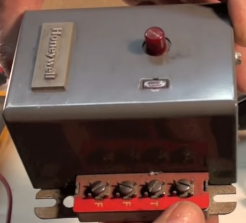
So, I have an original(?) Honeywell controller. It has two T terminals, and two F terminals:
The T's go to the thermostat... one provides constant 25v (or higher, mine is 30v), the other is the return to complete the circuit. The constant 25v ties directly to one terminal on the low voltage side of the transformer inside the controler, the return ties into the internal components (limit switches, relays, etc.) that control the furnace components (motors, ignition, etc.)
The F's go to the flame sensor. One terminal is likewise tied into the internal components. However, the other is tied directly to the OTHER terminal of the low voltage side of the transformer.
You should be able to find the electronic schematic for newer controllers in the technical documents on the Honeywell website. Here is the manual for the R8184G Protectorelay controller:
https://customer.honeywell.com/resources/techlit/TechLitDocuments/69-0000s/69-0617.pdf
As you can see on page 1 (refer to following image), the schematic shows direct lines to the low voltage side of the transformer to the terminals as I described above. From the schematic, the outer two terminals are the two terminals of interest. I probed the outermost two terminals on my older vintage controller with a multimeter, and sure enough, I got 30v.
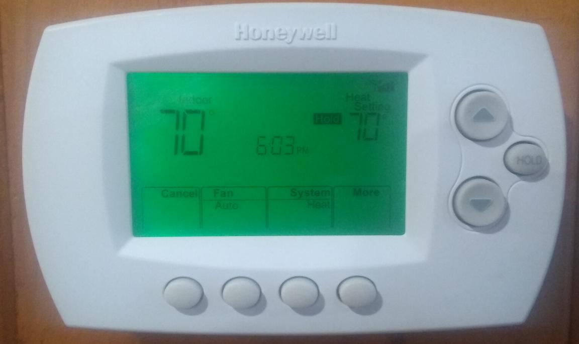
What does this mean? It means you can use the outer F terminal as a C wire for thermostats that need a C wire. I have a Honeywell RTH6580WF WiFi thermostat that I'm trying to get working with my ancient furnace.
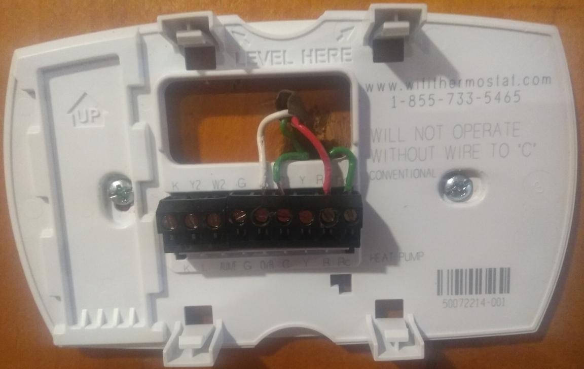
Luckily, I had an unused third wire (green) in my bundle, so I attached it to outer F at the furnace to use as a C wire. The red wire is attached to the outer T, and the white to the inner T. The red & white were originally reversed, so I swapped them at the furnace. So, red is in essence tied to the transformer, and carries constant power.
At the thermostat, the white simply attaches to W (heat), the red attaches to R (power), and the green attaches to C (common). Since the thermostat also needs power to Rc, I needed to use the jumper from R to Rc. For some reason, my thermostat did not include the factory made jumper (it looks like a small staple), so I just used a short piece of wire (the little U-shaped green wire).
Presto-chango, thermostat powers on.


