0

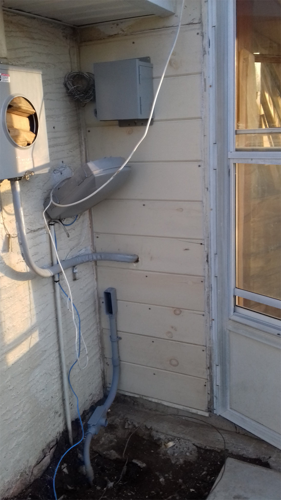
I finally got around to figure out the spot for a new transfer switch which I acquired some time ago, there aren't any choices since the transfer switch needs to be close to the meter. It is a small 5000 watts transfer switch (comes with relatives short wires), and it needs to be installed outside, and the only location outside would be on the same wall (exterior siding) whereon the circuit breaker panel hangs inside (interior of the premises). But then this wall (shown in the pic) is narrow and is sort of cramped and crammed with wires and stuff (socket meter nearby, conduits going up and down). The transfer switch in this case is a metal box hanging up on the wood sidings (the circuit breaker panel is right behind it. But I am not sure if this spot is ok, and what would be the requirement of clearances if any.
enter image description here

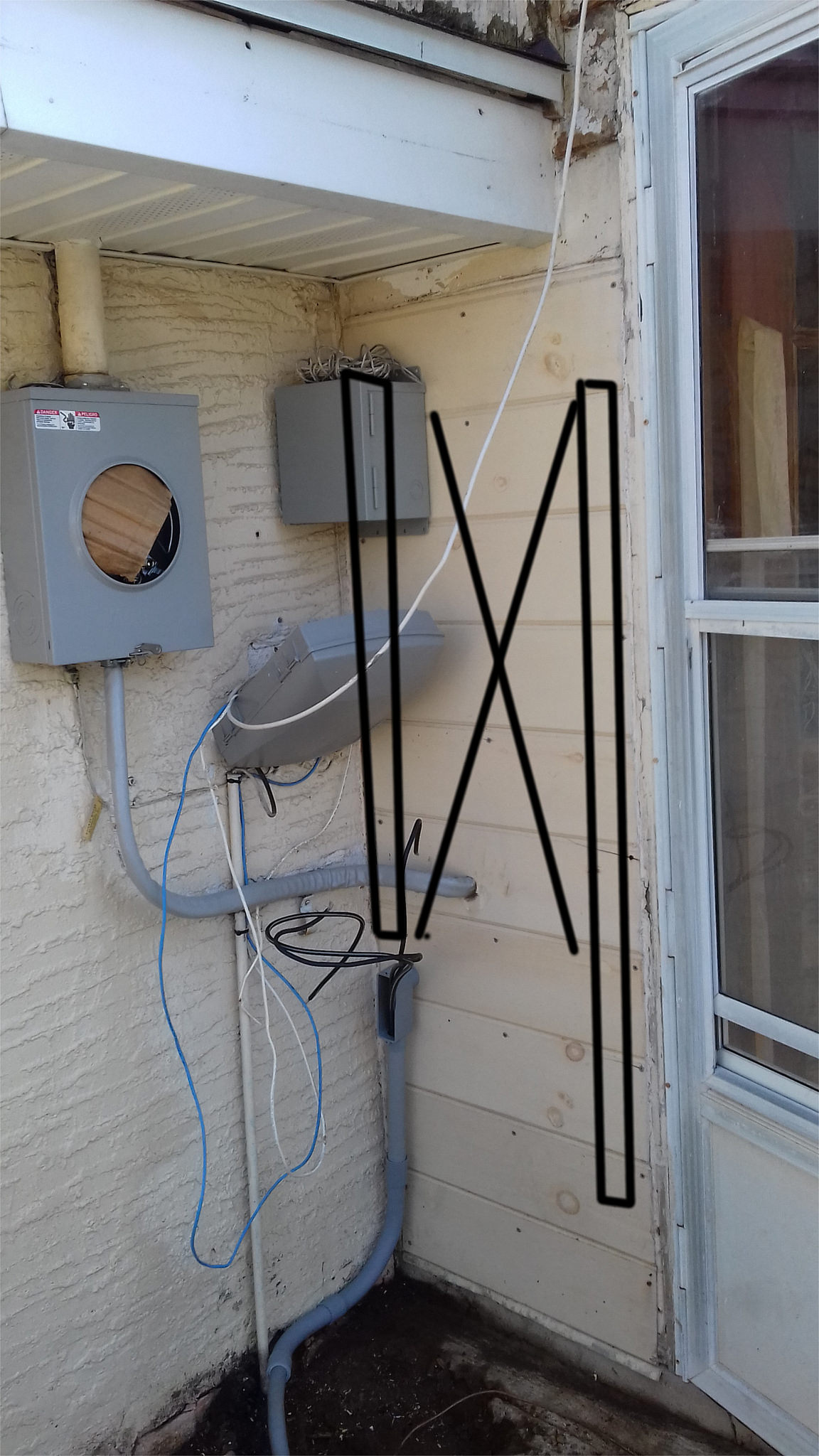
enter image description here

The area marked with an 'X' indicates the non-drilling area (breaker box present on the other side). The areas marked with a rectangle shows area passive to be drilled in order for conduit and wire to travel to the other side and enter the circuit breaker panel.

================ ADDENDUM =========== 02/13/2016

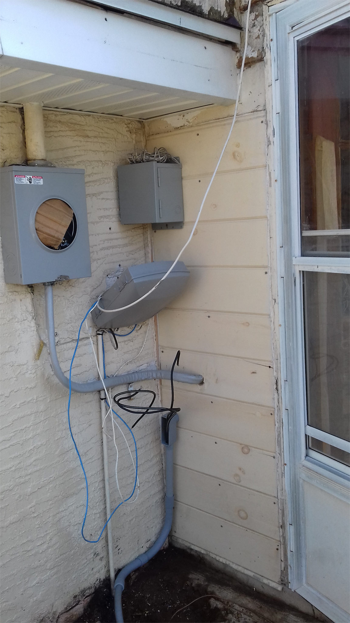
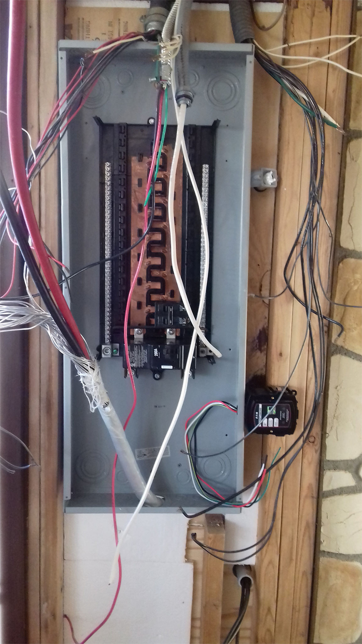
I moved the transfer switch box further to the right (complying with the clearance requirements), and used ¾ PVC conduit which then travel sideways few inches from the transfer switch box towards the left and enters the inside of the room by means of a close 90 deg elbow through a bored hole in the siding. Inside the conduit protruding from the bored hole has yet another close 90 elbow which will then with a small section of conduit enter the breaker panel using a knockout on its side. The pics below depict the inside and outside scenarios:

enter image description here

enter image description here

The pic of the outside also shows a ¾ underground pvc conduit along with wires coming from garage subpanel. Originally the pvc conduit protruding from the ground is ¾, but in order to make it easy to fish the large caliber aluminum wires from the ground conduit to the circuit breaker panel inside I decided to transition to 1" pvc conduit. Initially I simply put an adapter/fitting to transition, but was told that would not be acceptable (it is not clear why though) to simply use an adapter and that I would have to use an electrical box (in this case a L box) to transition. Using a L-Box also meant that I could not use the 45 degrees elbow initially planned to exit the ground, so aesthetically it does not look as intended, but hopefully it is acceptable. Any insight about the this approach or any possible discrepancy would be very welcomed.

3
  • What kind of transfer switch? Does it have lots of individual breakers, or just one breaker to switch over the entire household load?
    – longneck
    Commented Feb 1, 2016 at 15:24
  • It's a Reliance Controls CSR202 Single Circuit Transfer Switch, 5000-Watt, pre-wired, all-in-one transfer switch that can be connected to one 20amps 240V circuit or two 120V 20 amps circuits. It only has two switches in the transfer switch itself with three modes, and it comes with nema type L14-20 socket to connect the portable generator to it. Problem be I can not put it in the center of the wall given that can not drill a hole for the wire to travel to the other side given that the circuit breaker box occupies give most of the center area of the wall on the other side (interior).
    – tk3000
    Commented Feb 1, 2016 at 21:47
  • And putting it besides the door would make it on the way of the entry door itself. Only other option would be to put the transfer switch on the center of the exterior wall/siding (assuming it is ok for it to be there) and use a pvc conduit to bring the wire sideways and then inside.
    – tk3000
    Commented Feb 1, 2016 at 21:47

2 Answers 2

2

Simply move it further towards the right on the wall (closer to the door) so that it clears the meter and you're good.

The clear space required is...

  • Depth: 36" [NEC 2014 110.26(A)(1)]

In front of the box. As long as you're over to the right far enough that the meter isn't directly in front of the left corner of the transfer enclosure, you're clear.

  • Width: 30" [NEC 2014 110.26(A)(2)]

Beside the box. This can be measured from the center or either edge of the box. You'd want to measure from the left edge of the box towards the door for your clearance. It also requires clearance enough for the door on the box to open to 90° (which it seems there is)

  • Height: Not an issue [NEC 2014 110.26(A)(3) (Exception 1)]

Normally your clearance zone is from the floor/grade to 6-1/2' (or to the top of the equipment being installed, whichever is higher). I believe the eave there might not be tall enough, but exception 1 allows service equipment (less than 200A) to be installed at existing dwelling units with less than the required height. Although this could be up to interpretation and could pose issues with [NEC 2014 110.26(E)(2)(a)]

Also, per the wires and conduit, they are allowed to enter the clearance up to 6" in front of the box - which they appear that they would not. So they're also fine. [NEC 2014 110.26(A)(3)]

6
  • TFK: thanks a lot for your comments, I will look into all of that.
    – tk3000
    Commented Feb 1, 2016 at 22:39
  • @tk3000 Sorry, I see your image now with the X. Regardless of where the main panel is, the transfer switch can't go in the corner. But what about mounting it on the X and then running conduit through to the other side beneath it? Or even, mount the transfer switch lower to the ground below the X.
    – TFK
    Commented Feb 1, 2016 at 23:02
  • TFK: I see your point about it not been able to be at the corner and thus have its working space severe constrained by the meter socket box NEC 110.26(A)(1). The current of the transfer switch is: 1) measure from the bottom of the box to the grade => 56"; 2) measured from the top of the box to the grade => 68", besides it is only a 40amps capable device. So, I would assume that the height would be ok, and that I could simply move the 6" box to the right (towards the door), and then use a pvc conduit to connect to a hole at the corner of the exterior wall. The wall(siding) is about 2 foot wide
    – tk3000
    Commented Feb 2, 2016 at 20:05
  • The socket meter box has only 5" of depth, thus moving the switch 6" would clear the front of the switch box from the socket meter box, and still allow the door of the transfer switch box open at full 180 degrees. Does it sound acceptable?
    – tk3000
    Commented Feb 2, 2016 at 20:07
  • 1
    Exactly, moving it over 6" will work then. Also, the door does not count as an obstacle because it can be closed. Just think of them as flat walls when it comes to clearances.
    – TFK
    Commented Feb 3, 2016 at 3:29
1

I think your location may have more than 1 issue. Normally the maximum height is 6-1/2’. The door on the transfer switch must be able to be opened to 90 Degrees. The space in front of the opening usually requires 36”. These requirements are in the NEC 110.26(a)(1), 110.26.2 & 110.26.3.

6
  • Ed Beal: thanks for your inputs. I am was affraid it would not comply with clearances requirements. Problem be I can not put it in the center of the wall given that can not drill a hole for the wire to travel to the other side given that the circuit breaker box occupies give most of the central area of the wall on the other side (interior)
    – tk3000
    Commented Feb 1, 2016 at 21:49
  • And putting it besides the door would put it on the way of the entry door itself. Only other option would be to put the transfer switch on the center of the exterior wall/siding (assuming it is ok for it to be there) and use a pvc conduit to bring the wire sideways and then inside towards the circuit breaker box.
    – tk3000
    Commented Feb 1, 2016 at 21:51
  • I moved the transfer switch box further to the right, and used ¾ PVC conduit which then travel towards the left and enters the inside of the room through a bored hole. Inside the conduit protruding from the bored hole has close 90 elbow which shall enter the load center sideways from a knockout.
    – tk3000
    Commented Feb 14, 2016 at 0:37
  • The pics below depict the inside and outside scenarios: !Valid XHTML ![Valid XHTML]farm2.staticflickr.com/1525/24873447832_72b13d8b86_k.jpg). Any insight about the this approach or any possible discrepancy would be very welcomed.
    – tk3000
    Commented Feb 14, 2016 at 0:40
  • Bad link , I mess up all the times on these make sure no spaces between brackets and text
    – Ed Beal
    Commented Feb 14, 2016 at 0:47

Your Answer

By clicking “Post Your Answer”, you agree to our terms of service and acknowledge you have read our privacy policy.

Not the answer you're looking for? Browse other questions tagged or ask your own question.