1

enter image description here

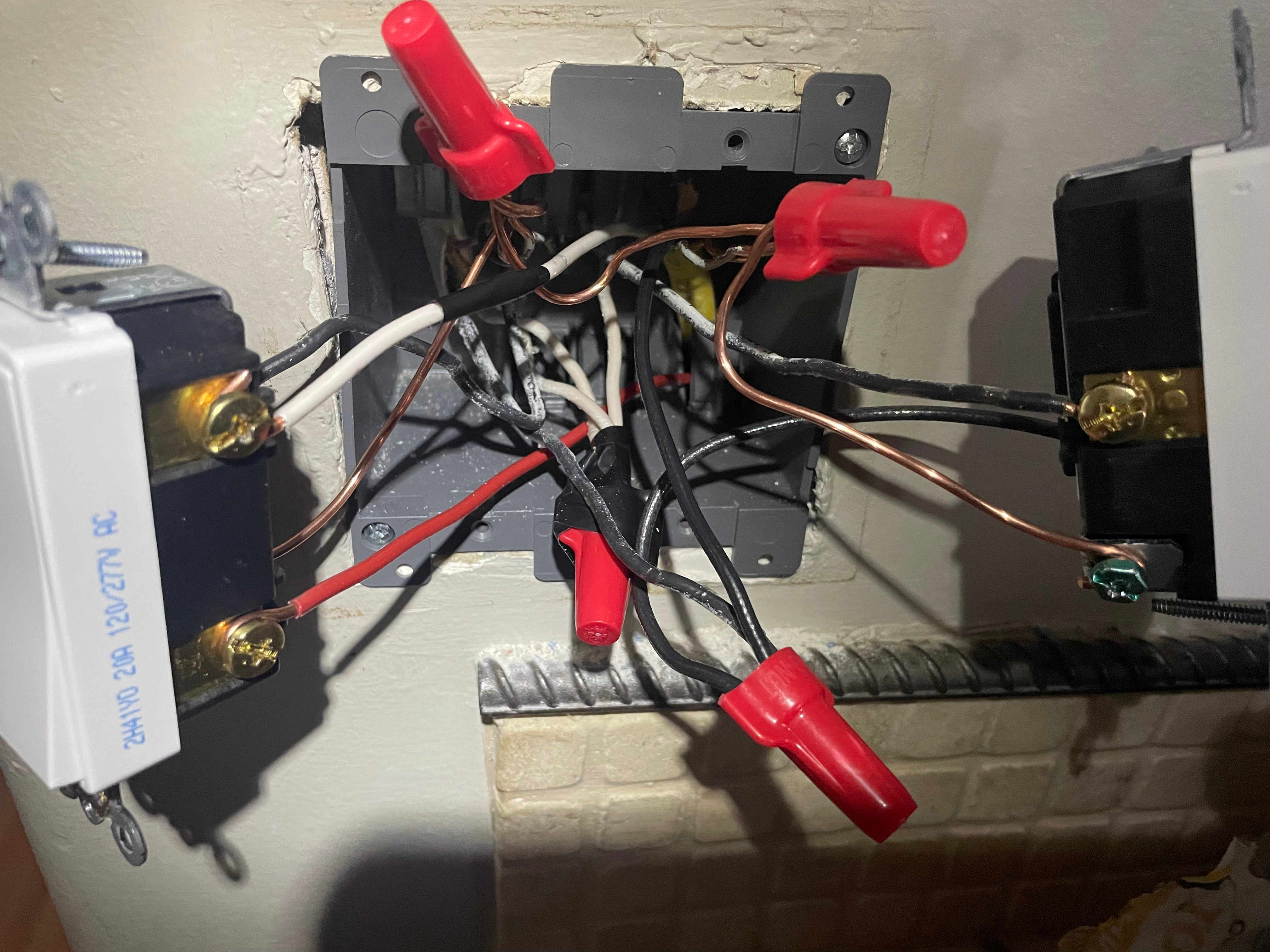
I have the above setup wired up. Here is a picture of the actual wiring of the right gang box.

enter image description here

But, the switches are clearly not wired correctly. What I am seeing when I test the switches is:

1 - the switch in the far left of my diagram

2 - the switch in the middle of my diagram

3 - the switch in the far right of my diagram

A - light on the left in my diagram

B - light on the right in my diagram

1 2 3 A B
1Up 2Up 3Up ON ON
1Up 2Up 3Down ON off
1Up 2Down 3Up off off
1Up 2Down 3Down off off
1Down 2Up 3Up off off
1Down 2Up 3Down off off
1Down 2Down 3Up ON ON
1Down 2Down 3Down ON off

Looking at these results, light A is only on if the two 3-way switches are in the same configuration (both up or both down), regardless of how the single pole switch is configured. Light B is only on if the two 3-way switches are in the same configuration (both up or both down) AND the single pole switch is in the Up position.

I even climbed up into the attic to make sure there aren't any wires connecting the 2 lights. I can't figure out what in the world is causing these results. I especially can't understand how the second light (the one connected to the single pole switch) is being affected by the other switches.

2
  • Looks like switch 3 is wired in series with switch 1 & 2 circuit. (both the 1 & 2 switchover must be on, both switches in the same position, AND switch 3 for light B to be on, according to your truth table).
    – Unimportant
    Jan 3, 2022 at 23:01
  • Use a voltmeter or voltage detector to examine the wire-nut with the three black wires (lower right in your photo) to see if it is always hot or if it is hot only when light A is on. You can also disconnect the black wire from the common terminal of switch 2 and test it for constant-hot. Jan 4, 2022 at 3:11

3 Answers 3

5

Any color you want, as long as it's black.

- Henry Ford

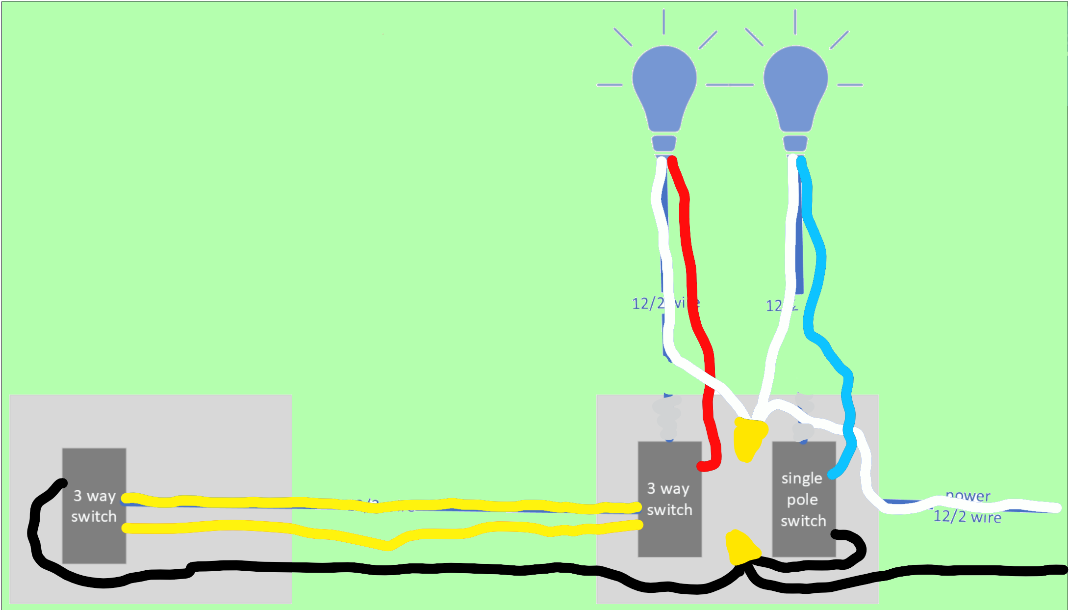
No wonder you're confused. You have black wires doing 3 different functions. Let's grab our handy-dandy 5-pack of colored electrical tape, and re-mark the wires according to the job they are there to do.

enter image description here

  • Black for always-hot
  • White for neutral (required per Code)
  • Red for switched-hot 1 (hot when you want that lamp 1 on)
  • Blue for switched-hot 2 (hot when you want lamp 2 on)
  • Yellow for the 2 travelers in a 3-way setup.

enter image description here

(standard 3-way diagram)

So let's re-mark the wires as needed with colored electrical tape. Now your drawing looks like this.

enter image description here

I only colored, I didn't change any wire routes... and so your drawing was completely correct. What went wrong is the confusion of black wires.

There is one special exception in wire marking. Your 3-way "spur" has white but it isn't neutral. In that case, white must be Always-Hot.* So, paradoxically, the white wire must be marked black** - and the black/red wires should be marked yellow.

Note that the use* and re-marking** of white wire black/always-hot is a Code requirement, not a Harper-ism. All other wire color markings are optional and are merely my suggestion.


* Use white for always-hot: NEC 200.7(C)(1) sentence 3.

* Re-mark white: NEC 200.7(C)(1) sentence 1-2.

8
  • The white wire I am using as a traveler is marked with black tape. When you say "your drawing was completely correct", I'm not sure what "completely correct" means since this is how it is wired right now, yet it doesn't work as expected.
    – irrational
    Jan 4, 2022 at 0:41
  • @irrational What Harper is saying is that (and I agree - I traced it out myself before reading Harper's answer) your drawing (except for the black/white color issue, but electrically correct even if not code compliant) shows the desired functionality. Which means that since your truth table has different results, you must have some wires connected different from the way the diagram has them. Jan 4, 2022 at 0:50
  • I absolutely do not have them connected differently. I've been looking at it and tracing back every single wire at least 6 times over the past 2 days. There is no possible way it is wired differently than the diagram indicates. Also, @Transistors comment below indicates that the way it is diagrammed/wired right now is incorrect. I just don't know the correct way to fix it.
    – irrational
    Jan 4, 2022 at 0:54
  • Marking the white wire is not enough @irrational, it also must be swapped so it is the always-hot common, and not a traveler. Jan 4, 2022 at 1:02
  • 1
    Are you sure you haven't confused the supply hot cable with lamp 1 or lamp 2 cable? Also the red wire appears to be exiting the box not in a cable sheath... what is up with that? Jan 4, 2022 at 1:04
3

schematic

simulate this circuit – Schematic created using CircuitLab

Figure 1. What you want.

schematic

simulate this circuit

Figure 2. What you've got.

8
  • I understand that I need to change how the black wires are connected, but it's not clear to me how I do that. The power line is coming into the gang box that contains SW2 and SW3. Is this saying that I need to run a new line from the panel to the gang box that contains SW1? I hope not since that is about a 70 foot run.
    – irrational
    Jan 3, 2022 at 23:20
  • 2
    @passerby, I rolled back your edit. The convention is that captions go below the figures.
    – Transistor
    Jan 3, 2022 at 23:28
  • 1
    @irrational, I don't know. You'll have to figure it out. My Figure 2 is the most likely explanation.
    – Transistor
    Jan 3, 2022 at 23:33
  • 2
    @irrational aaarrrgh ... please do not ask does anyone know? ... that is a poll question that does not really ask about the problem ... please ask what is the correct way to ..... ? ... that is a question about the problem
    – jsotola
    Jan 3, 2022 at 23:44
  • 1
    @irrational - I agree with Transistor's diagnosis of your issue, and I think how you've got there is by mixing up 2 of your cables. I think you've confused the bottom-right "power in" cable with the top-left "3-way switched lightbulb" cable. If you swap those 2 connections over (wire-nut with 3 blacks and 3-way switch common terminal) it'll probably all work as you intend it to.
    – brhans
    Jan 4, 2022 at 1:29
3

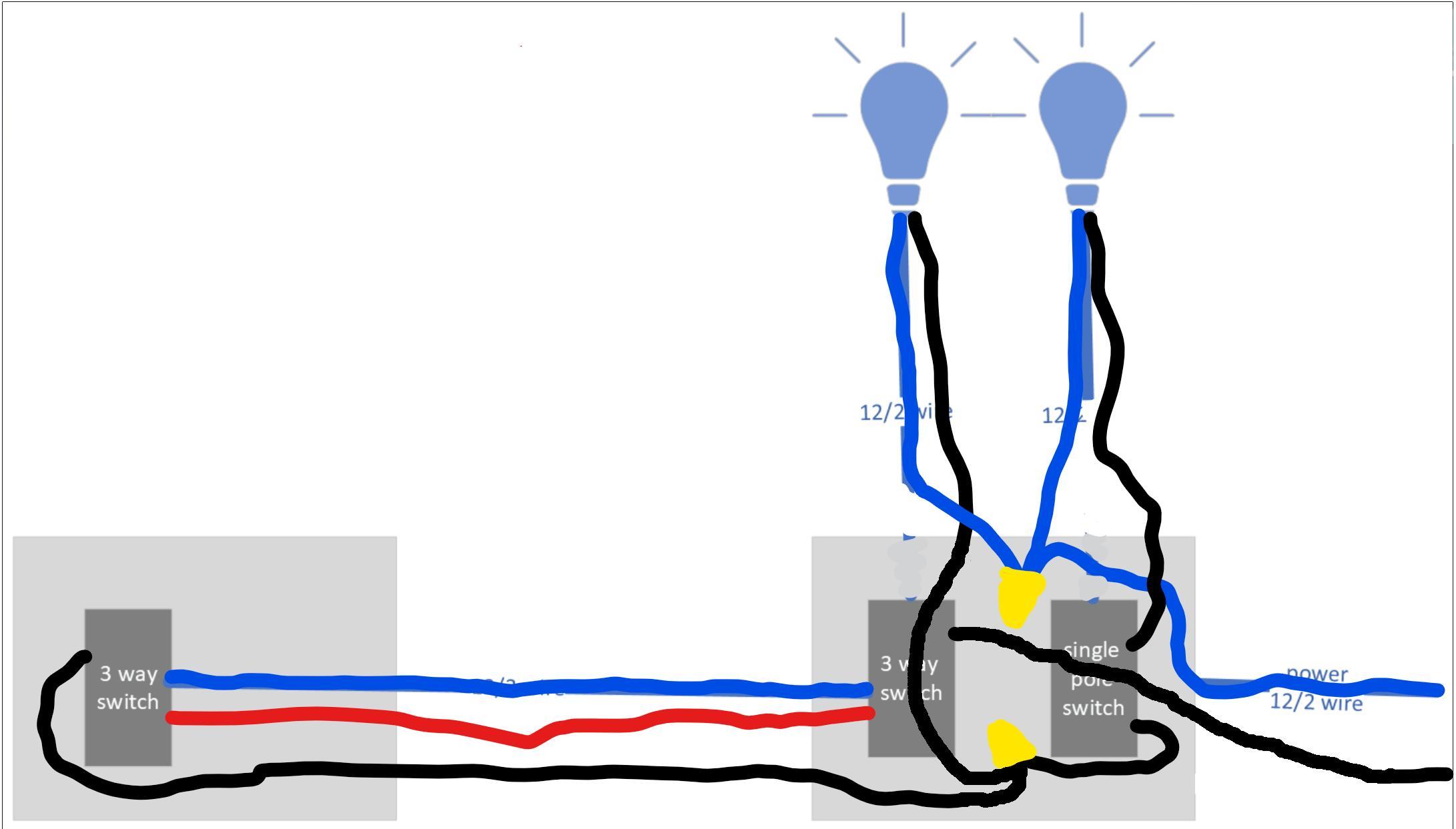
Your wiring diagram is in irreconcilable conflict with your truth table. I think your truth table is correct and your wiring diagram is wrong. Your circuit is actually wired like this:

corrected diagram

As @Harper-ReinstateMonica has commented, you have mixed up the light-A cable with the power-in cable.

Power goes first to the common terminal of the near 3-way (switch 2), then via the travelers to the far 3-way (switch 1). The black wire in the 3-wire cable is not a constant-hot to switch 1, it is the switched-hot returned from switch 1.

You may find it hard to believe that you could have misdiagnosed your wiring this way, but this is one of those cases where you can stare at an error for days and not see it, while the first ignorant yahoo who comes along and looks over your shoulder points it out immediately.

You can verify this diagram by disconnecting the black wire from the common terminal of switch 2 and testing it for constant-hot.

Once you have correctly identified all the cables and wires, you should have no trouble connecting everything up according to the diagram in your question, which, as you have maintained all along, should work properly.

And you don't need to run any more 70-foot wires.

1
  • I see where @brhans, in a comment to Transistor's answer, has arrived at the same conclusion. Jan 4, 2022 at 3:21

Your Answer

By clicking “Post Your Answer”, you agree to our terms of service and acknowledge that you have read and understand our privacy policy and code of conduct.

Not the answer you're looking for? Browse other questions tagged or ask your own question.