0

In a previous question on here I was trying to figure out why my basement radiators weren't working. With everyone's help I was able to figure out that the zone valve on the pipe which came from the basement radiators was not working. I still need to dig a little bit more into WHY it is not working (does it need to be replaced, etc), but I was able to determine that if I manually slide it to "open", those radiators will work. So now I'm already thinking about the next step.

I have two zone valves which could control the two zones of my house separately, but I have a "dumb" thermostat which can't do that, and also it'd be somewhat difficult to run extra wires up to the first floor and connect with the thermostat up there to control a separate zone. What would be much easier is to install a separate thermostat downstairs in the half finished basement. I can easily reach the backside of one of the finished walls, add a thermostat, and then run wire from there to the heating system to control the basement 'zone'.

So my question is: How? I've a attached a diagram of the current wiring setup below and I'd love it if I could get help with two specific things,

  1. Does the current diagram look properly wired (or could that be contributing to why the basement zone valve isn't working)
  2. Where on that diagram could I add a second thermostat which would control the basement radiators?

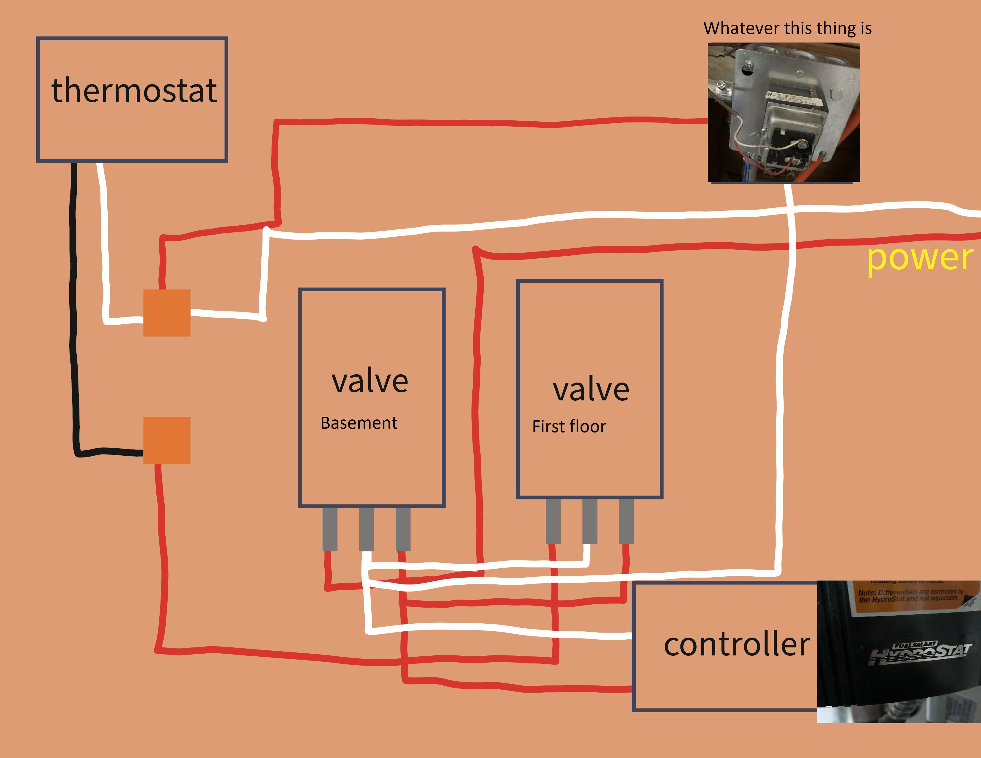
Current wiring: enter image description here

1 Answer 1

2

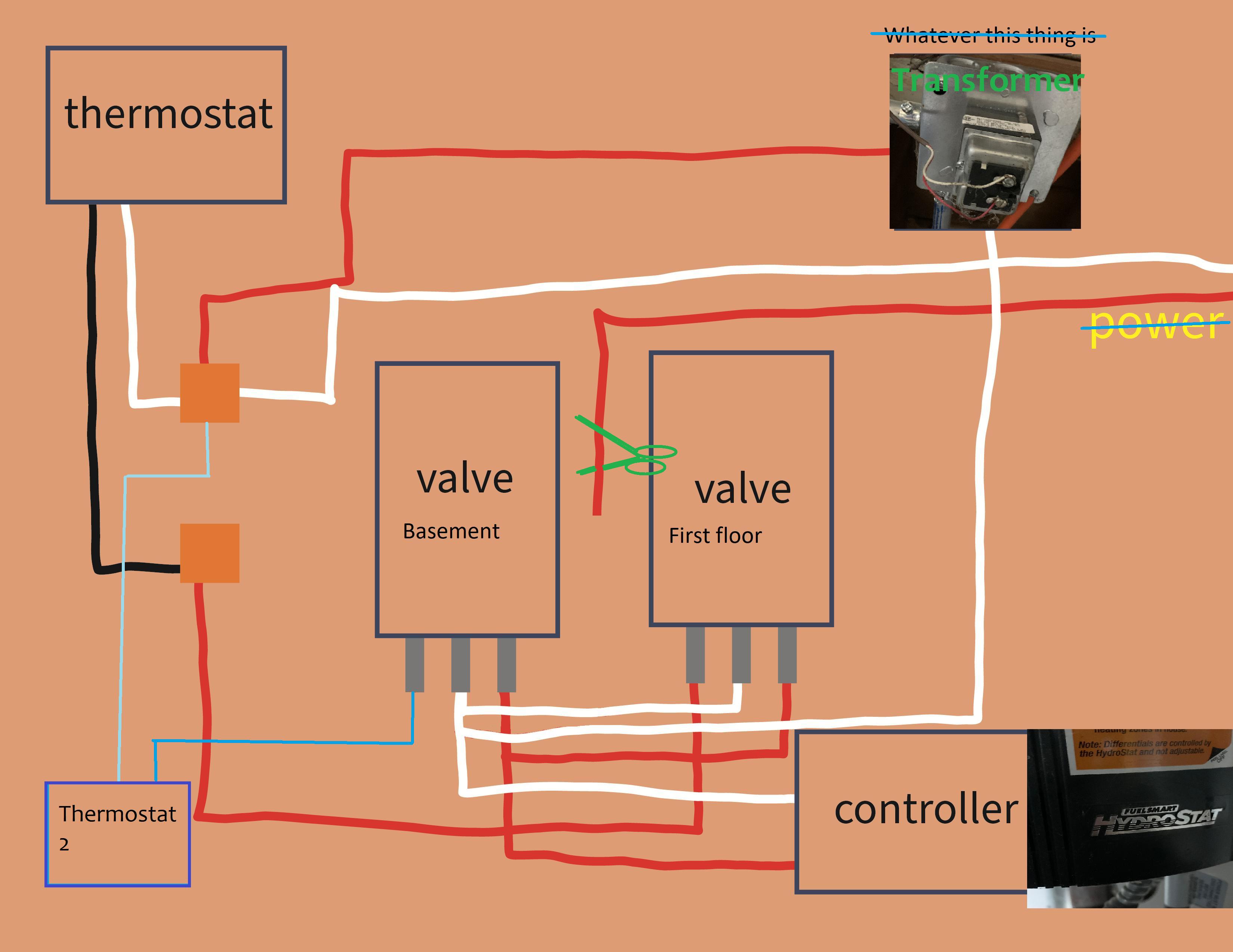
You're close, but in order to wire up the basement valve you need to make some changes. I modified your diagram and added a crude green scissors showing "eliminate this connection" between "power" though I'm not sure what you mean by that, and what appears to be the basement valve's thermostat relay (if it's on the left just like the first floor's valve).

The new thermostat (blue) should connect to the White line wirenut at the top, the same as the input to Thermostat 1, and the output should go to the input of Basement Valve the same as the Thermostat 1 output connects to its valve.

Also in blue, I scratched out your "whatever this is" and labeled it in green, and scratched out "power" because that's probably not correct - power should come from the Transformer instead, it's likely 24VAC.

enter image description here

4
  • So.... when I saw your answer I was at work and couldn't look at everything to double check my diagram, so I just thought to myself "yea he's probably right about it not going to the circuit breaker (power)"... but when I just checked at home right now.... I'm 99% positive it does. There's like a ten foot gap where I can't follow it, but honestly I'm 99% sure it connects to the circuit breaker panel. I totally believe you that it SHOULDN'T in a working system, and also as I mentioned above one of the valves doesn't work (and it happens to be the one its connected to). Commented Dec 30, 2021 at 23:34
  • , so in other words.... that MAY be the problem. Commented Dec 30, 2021 at 23:36
  • IMO it's more likely that power goes to that transformer and not directly to the valves. If you have a voltmeter you can double-check. This kind of transformer is used often for thermostats and sometimes double-purposed to drive doorbell circuits as well. Commented Dec 31, 2021 at 14:53
  • When I just disconnected the power from the breaker and connected the valve that didn't work to the same connection from the thermostat that the other one had, everything now works great for both valves Commented Jan 1, 2022 at 0:09

Your Answer

By clicking “Post Your Answer”, you agree to our terms of service and acknowledge you have read our privacy policy.

Not the answer you're looking for? Browse other questions tagged or ask your own question.