3

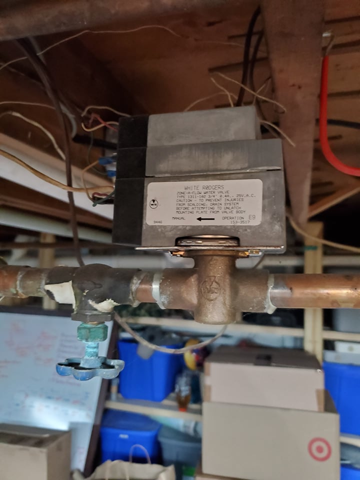
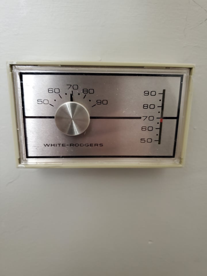
I have a fuel burner (fuel oil) that heats water and provides my home with baseboard heat. I have two thermostats and zone valves, both by White Rogers (and both pretty old): one set for the downstairs and one set for the upstairs.

I assume that each zone valve + thermostat pair is part of the same branch circuit and thus, controlled by the same breaker. If that's not the typical setup, please begin by correcting me!

But assuming I'm correct on that, I'm trying to figure out what breakers control both zone valve + thermostat pairs. My main service panel got upgraded last year but the electrician did a terrible job marking everything and did not mark where these were.

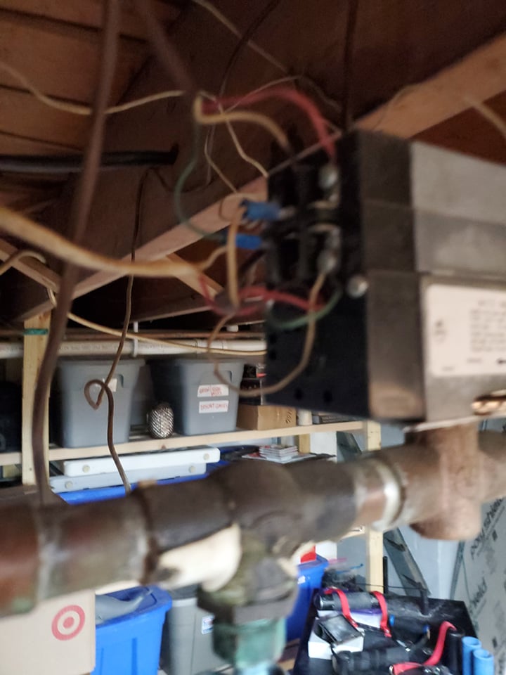
As opposed to lightswitches and outlets which are easy to test (turn a breaker off and see if a certain light goes out or if my electrical/volt pen doesn't detect any voltage in the outlet), I'm not sure how to test whether a particular zone valve and thermostat have power. Here is a picture of what they look like:

enter image description here enter image description here enter image description here

Can anyone give me a recommendation for how I could:

  1. Turn a breaker off; and then
  2. Check whether or not there's power coming to the zone valve and thermostat?

I have many breaker "candidates" for which ones could be controlling these valve/thermostat pairs, but currently I'm not sure how to test whether the breakers are/aren't supply power to them.

I suspect this will involve buying a multimeter. I used one in college for a class so I'm not a total stranger to them and wouldn't mind buying one if its the right tool for the job.

3 Answers 3

3

Multimeter would do the trick, and is a useful tool that does not cost much unless you go for the high-end ones.

Check for 24VAC (usually) on the thermostat wires (either disconnected, or with the thermostat turned down so it's not calling for heat.)

Usually there's just the one transformer providing the low voltage for all the thermostat(s) & controls, so if you find that breaker, which is usually also the one controlling all power to the "boiler" (which is what fuel-burning water heating devices are usually called unless they are "water heaters" for plumbing type water, even though most are not making steam these days) it should be all of them, but you can also check for 24VAC at the zone valves (usually with the thermostat calling for heat.)

In a code compliant install, the boiler circuit breaker should not be shared with any other circuits, so if you know (or find while looking for it, and improve the labeling) that a breaker turns off something else, it should not be the one for the boiler. So identifying which breakers control various other lights and outlets would both allow you to improve your labeling, and reduce the number of possible candidates for the boiler breaker.

5
  • Thanks so much @Ecnerwal (+1) -- I will grab a decent multimeter. I do actually know the specific breaker that my boiler is on, the electrician did manage to label that and I have tested/verified it. It also sounds like you are saying it is typical that all the thermostats and zone valves are rigged up to the same branch circuit + breaker. Please let me know if that's not typically the case. Commented Dec 14, 2021 at 14:16
  • Procedurally, it sounds like you are suggesting that I: (1) turn one of the thermostats all the way down so its not calling for any heat, (2) take the casing off of it to expose some type of 24VAC wires (???) and then (3) touch a multimeter to those now-exposed wires to see if anything registers. Is that the gist of it? If so, what setting should I put the multimeter on, just normal VAC? Or any particular range/level? Thanks again! Commented Dec 14, 2021 at 14:16
  • 2
    Range suitable for 24VAC - if not auto-ranging, something larger than that (50, 100 or 250 VAC, depending on your meter.) But odds are 99+% that the boiler breaker is the breaker they are on. Some thermostats you take the casing off of, others the front of the thermostat pulls off of (unplugs from) a backing plate where the wires are connected. For a typical old-school heat-only set up, it's often just red and white, and you check the voltage between them.
    – Ecnerwal
    Commented Dec 14, 2021 at 14:26
  • Beware, it could be one transformer per unit--we have combination AC/gas furnace units, one upstairs, one downstairs. Each thermostat is powered from it's corresponding unit. Commented Dec 15, 2021 at 1:11
  • Key point there being you have two units. So that makes perfect sense - want each unit to work independent of the other. With one boiler and two zones, there's no reason for it to be independent (might be two transformers, but still 99+% likely to be powered with the boiler circuit.)
    – Ecnerwal
    Commented Dec 15, 2021 at 1:16
3

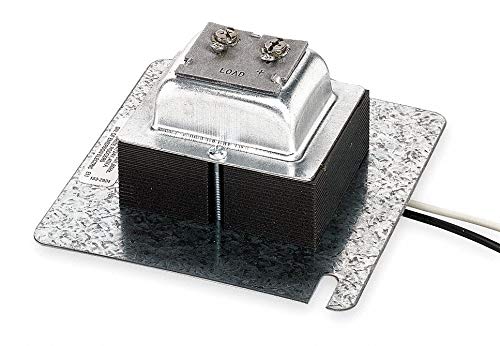
The Zone-A-Flow 1311 runs on 25V AC. That is also typical for thermostats in general - though many "dumb" thermostats don't even need any power at all. So what you are looking for is a transformer (possibly one for each zone). A typical White-Rodgers from Amazon:

Transformer

but brand doesn't matter, voltage matters.

Typically these will be powered by the same power for everything else in the HVAC system - e.g., electronic ignition, pumps, blowers, etc.

The binary method of figuring this out is:

  • Turn off 1/2 your breakers
  • If the device is still on, turn off 1/2 the remaining breakers
  • If the device is off, turn the off breakers on and the on breakers off
  • Lather, rinse, repeat

Since "dumb" thermostats have no indicator lights, a multimeter will be very helpful here in figuring out when your power is on/off.

2
  • Thanks @manassehkatz (+1) -- can you elaborate more on how (specifically) I could use the multimeter here (neither my zone valves or thermostats have indicator lights on them)? Commented Dec 14, 2021 at 14:19
  • 1
    Check AC voltage between pairs of terminals on thermostat or valve until you find which pair shows ~ 24V. Then check the same terminals with 1/2 the breakers off, etc. Commented Dec 14, 2021 at 14:27
3

I would think a simple non-contact voltage detector would tell you whether there's power running to the wiring.

  • While the power is on, determine which wire(s) are hot.
  • Turn off a candidate breaker.
  • Check to see if the hot wire(s) are still hot.
  • Lather, rinse, repeat until you find a breaker that kills the power.

Once you've determined which breaker(s) it is, double check with an actual meter, just to be sure.

4
  • Some NCVT start at 50V (which is basically the bottom of "considered dangerous") and won't detect the typical ~ 24V thermostat wiring. Commented Dec 14, 2021 at 13:29
  • 1
    Fair enough, @manassehkatz-Moving2Codidact. I saw your answer after writing mine. I do know there are line-voltage thermostats, so it could work there. Bonus because we both used "Lather. Rinse. Repeat". :)
    – FreeMan
    Commented Dec 14, 2021 at 13:35
  • Thanks @FreeMan, can you elaborate more on "Check to see if the hot wire(s) are still hot"? I guess I'm looking for a breakdown of the procedure such as: take case off and look for a wire that looks like X and another that looks like Y, touch the multimeter to X and Y, etc. Thanks again for any clarification here! Commented Dec 14, 2021 at 14:18
  • 1
    @hotmeatballsoup the non-contact tester will tell you which wires have power on them with the breaker on. Once a breaker is off, check those wires again. Double check each of them with a multi-meter. At the pump, I wouldn't think you'd need to disassemble anything, just touch the screw contacts with the meter, use the NCVT on each of the wires. Probably the same once you take the cover off the thermostat.
    – FreeMan
    Commented Dec 14, 2021 at 15:39

Your Answer

By clicking “Post Your Answer”, you agree to our terms of service and acknowledge you have read our privacy policy.

Not the answer you're looking for? Browse other questions tagged or ask your own question.