0

I've got a wiring setup that I'm trying to wrap my head around in order to replace the existing switches with a single smart switch (Inovelli Dimmer) and multiple Lutron Pico remotes. This will involve placing the smart switch in the desired location and only leaving the travelers to that switch hot and capping off the rest (or just leaving them all hot) and place a remote in front of (Lutron Caseta Pico).

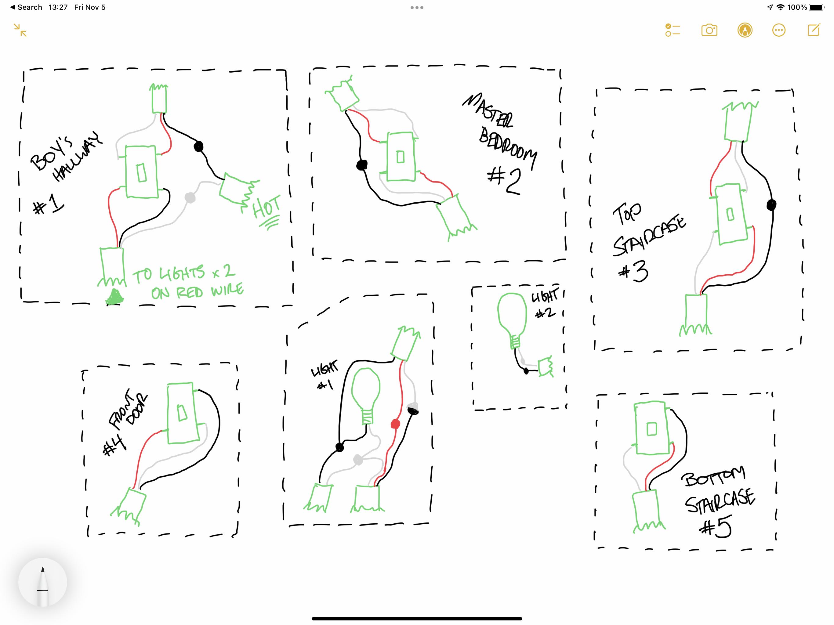
I have 3 x 4-way switches and 2 x 3-way switches. My load and source come into one of the boxes with a 4-way switch. It appears the lights are wired to use the red wire of a 14/3.

My questions:

  1. Is the wiring correct from how I have it drawn for the lights?
  2. It would appear that I have a traveler wire that is originating from somewhere that I haven't identified. Would a traveler branch from one of the lights and go to 2 switches?
  3. Ultimately, how would I wire this to place a single smart dimmer as a replacement for Switch #2? Unlike the drawings, I won’t be placing any other dumb switches in the circuit but will instead be using Lutron Pico remotes.

Excuse the crude drawing and thanks in advance.

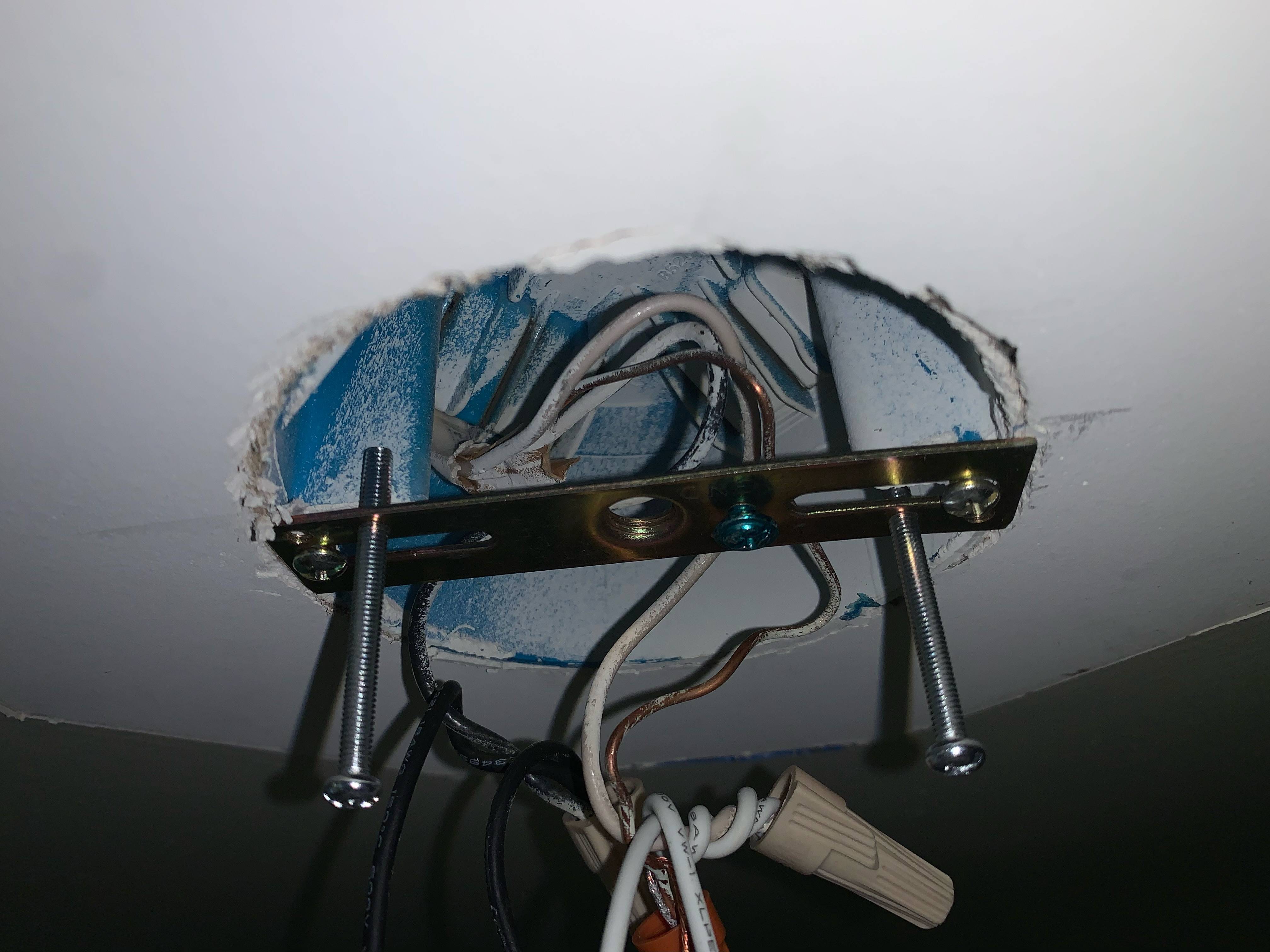
EDIT: Added pictures of the boxes and the lights and updated my drawing of the wiring. Light #1 is actually a ceiling fan / light combo. Currently it's an all on/off situation.

Here are the supplied wiring diagrams provided by Inovelli (more here): 4-Way 2-Way

Here is my current wiring: enter image description here

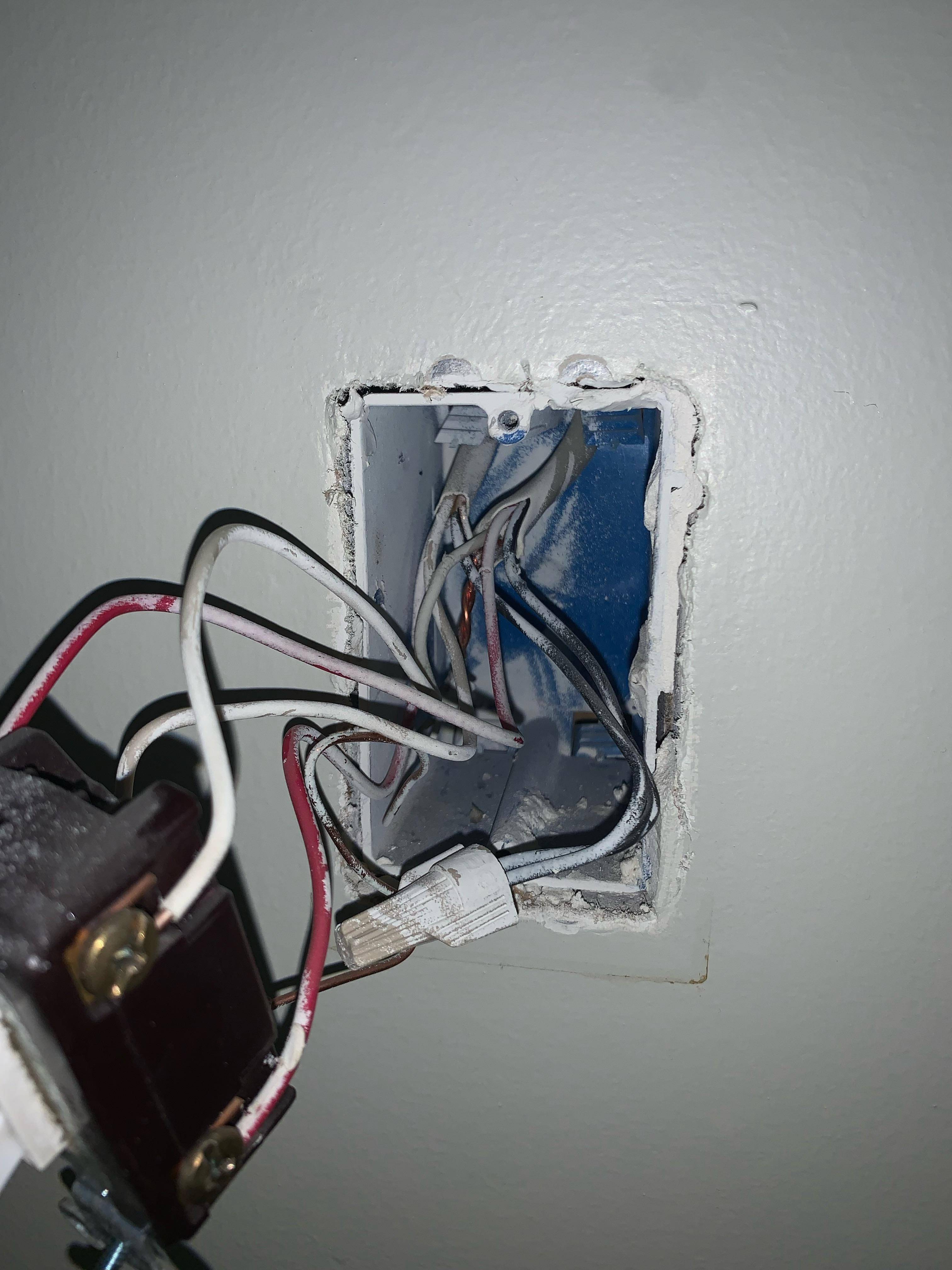
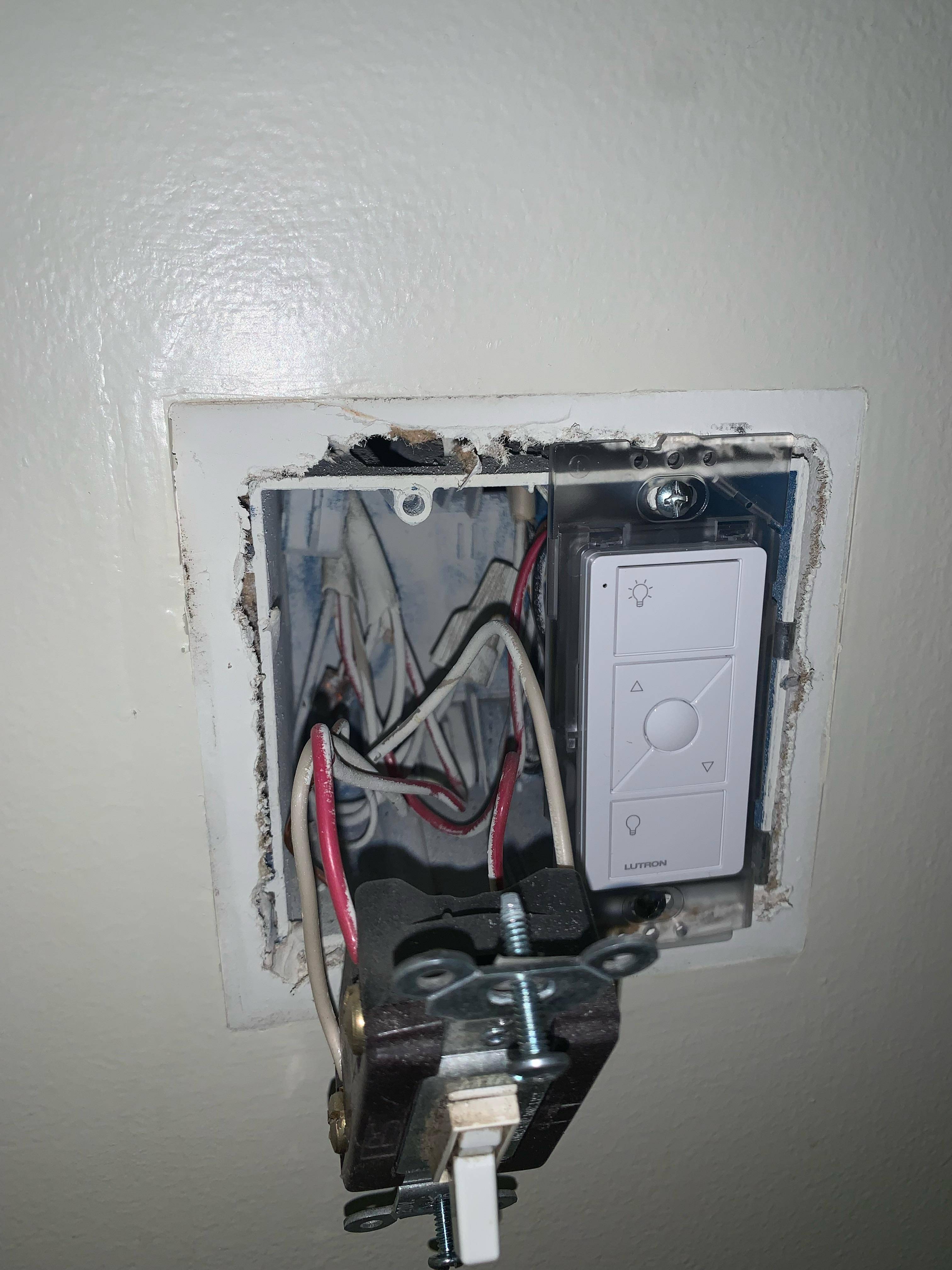
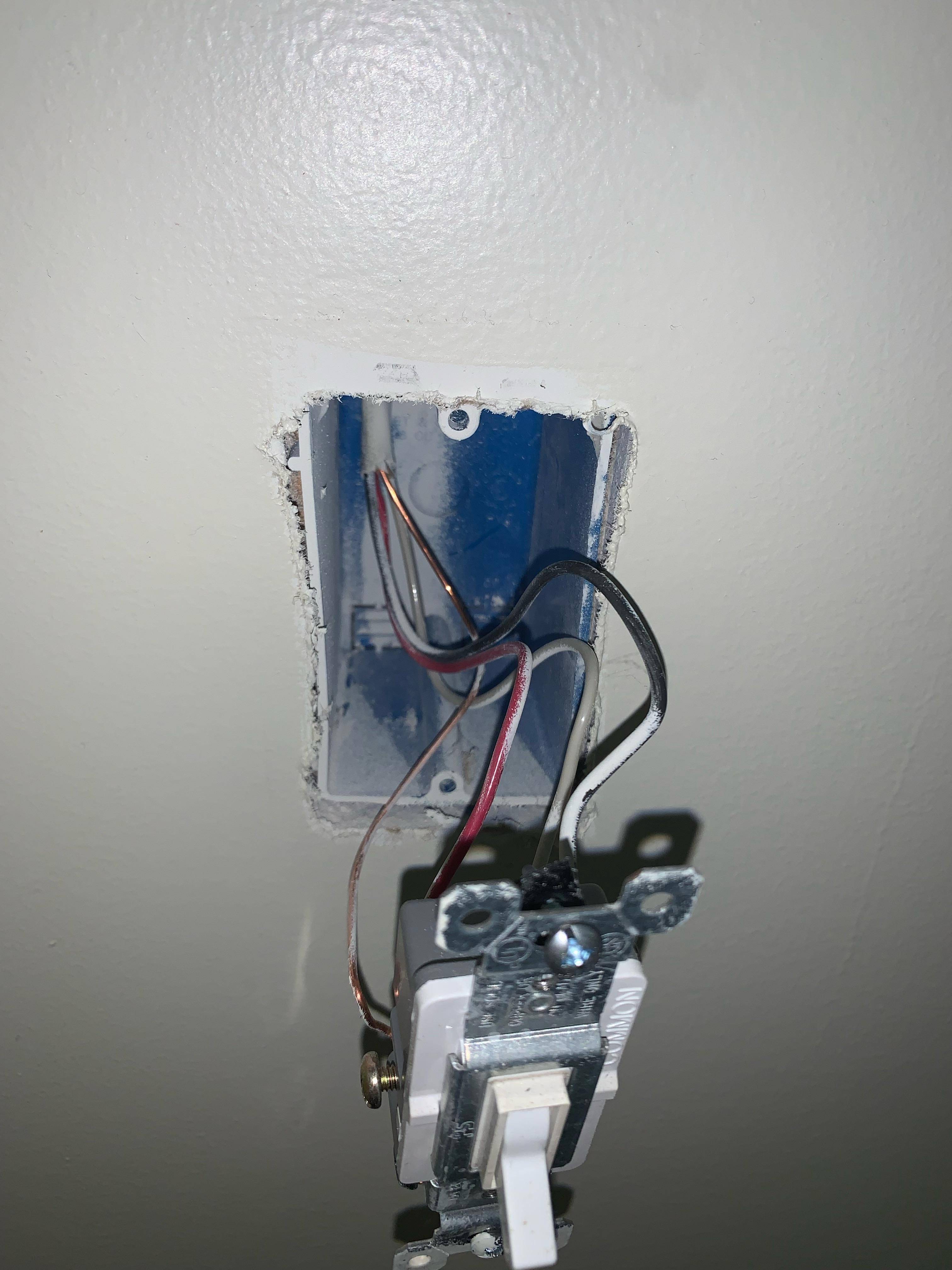
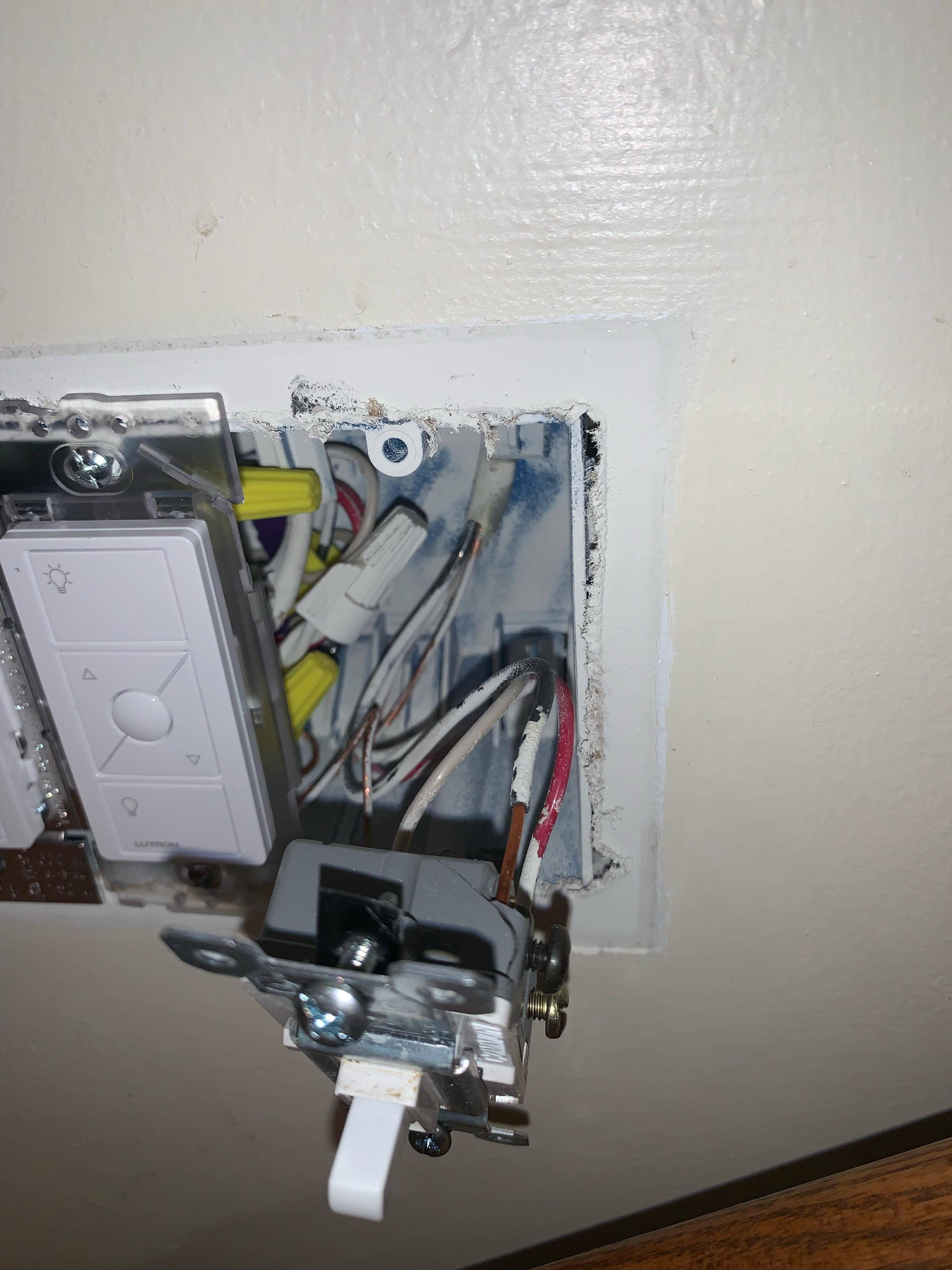
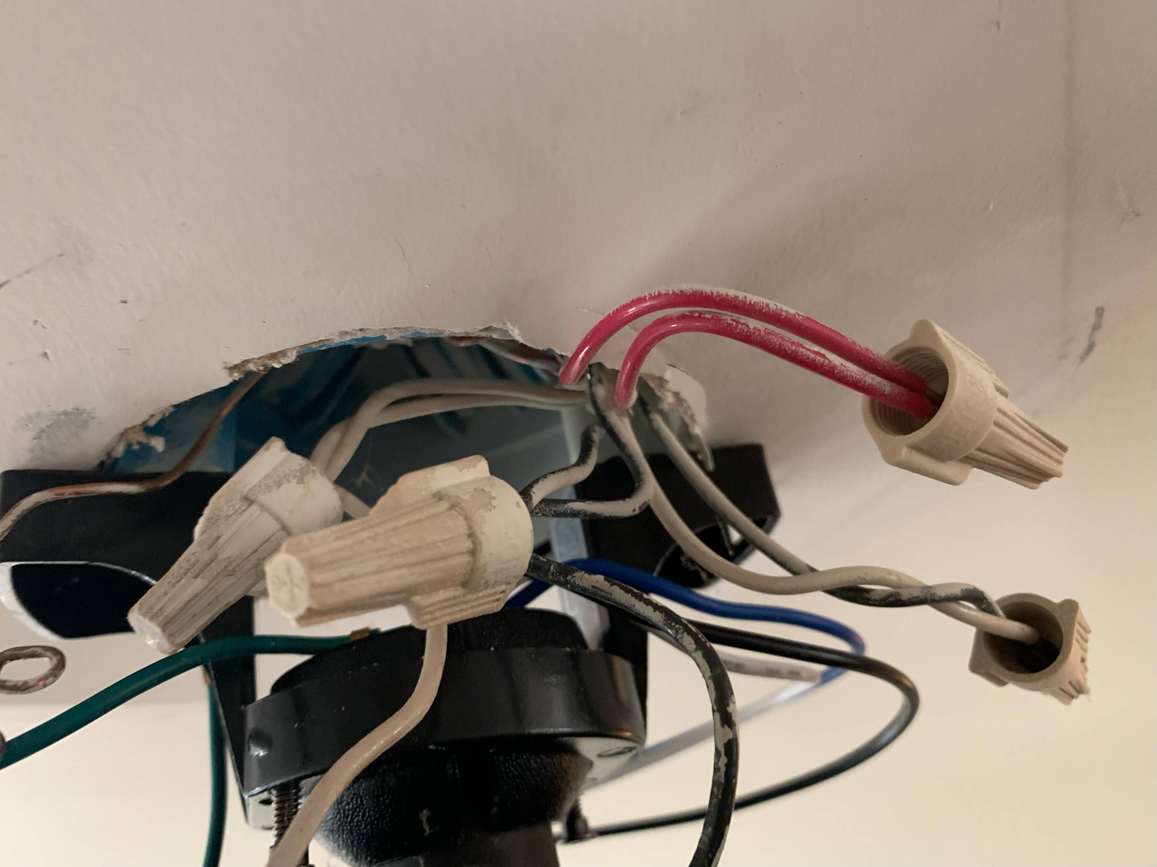
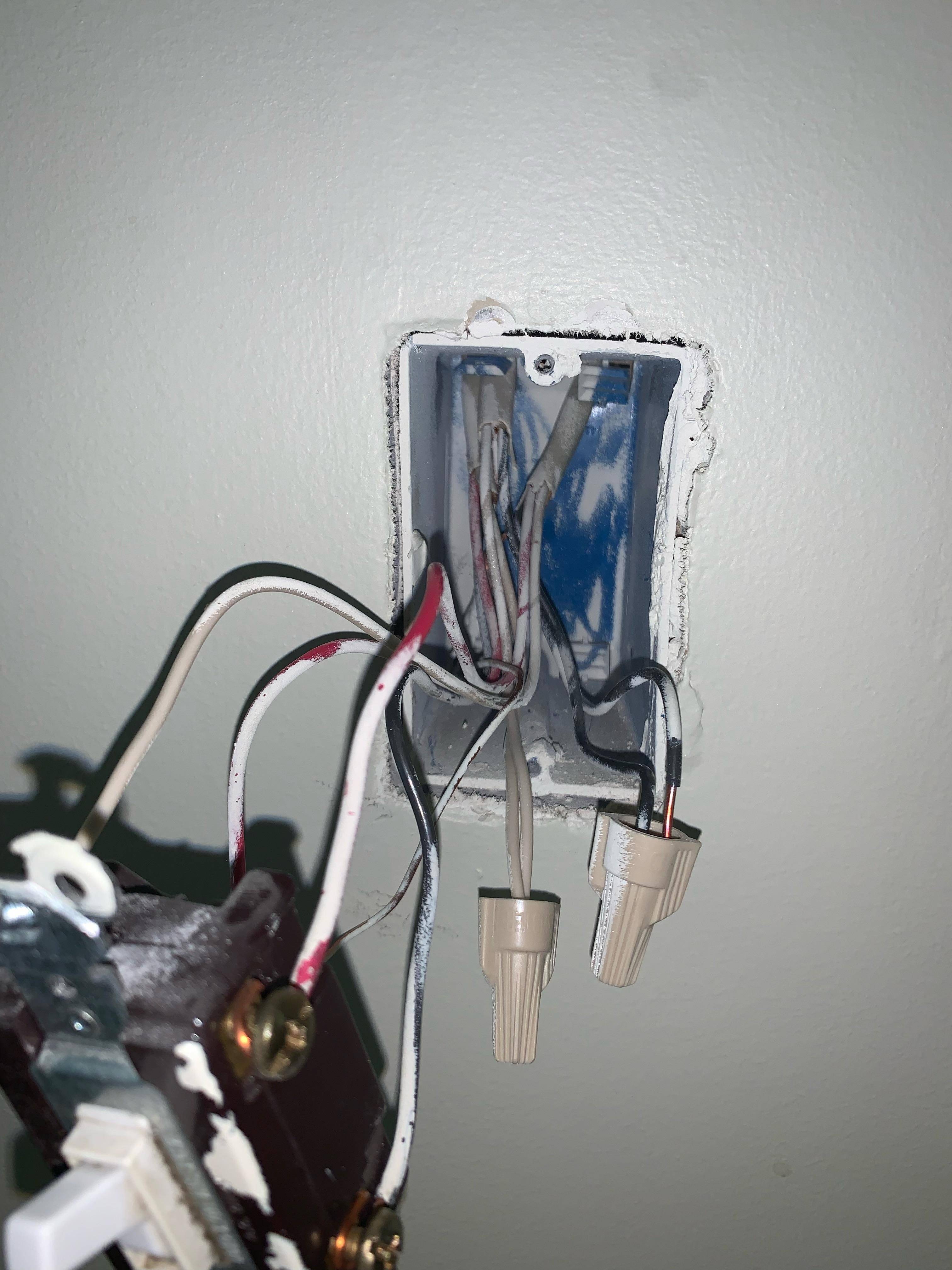
And pictures of each box: Switch #1 (Boys Hallway): Switch #1 (Boys Hallway) Switch #2 (Master Bedroom): Switch #2 (Master Bedroom) Switch #3 (Top Staircase): Switch #3 (Top Staircase) Switch #4 (Front Door): Switch #4 (Front Door) Switch #5 (Bottom Staircase): Switch #5 (Bottom Staircase) Light #1: Light #1 Light #2: Light #2
4
  • Can you post the link to the Inovelli docs saying it's compatible with the Pico remotes? Commented Nov 5, 2021 at 3:07
  • Also, can you post photos of the insides of the boxes involved please? Commented Nov 5, 2021 at 11:48
  • @ThreePhaseEel. It's not. I'll be linking the Pico remotes to the Smart Switch controlled lights through the use of a Home Assistant hub to handle the logic.
    – Russ W.
    Commented Nov 5, 2021 at 16:51
  • @ThreePhaseEel. Pictures uploaded. I currently have the switch #1 disconnected and the only hot line is the one with the nut attached. Not the one with the copper wire exposed sitting on top of the nut.
    – Russ W.
    Commented Nov 5, 2021 at 16:57

3 Answers 3

1

The original wiring

As drawn in the green diagram, that circuit can't work without doing something vile like a Carter circuit. Here is how 4-way circuits work.

enter image description here

Note that there are 2 travelers. One is hot and one is not. The 3-way and 4-way switch simply exchange which is hot and which is not. The 4-way switches repeat as many times as necessary.

Since you have 2 lights, you would need to have /4 cable between them: 2 travelers (to pass through), switched-hot, and neutral. The only way to make that function with /3 is to misuse safety ground as the neutral current return, which is rather dangerous.

Junk it, go smart switches.

Use smart-switch masters and remotes that are all designed to play well together. Also, use units that are designed to use wireless or power line signaling. Reassign wire colors as follows:

  • White = neutral in all locations
  • Black = always-hot in all locations
  • Red = switched-hot from smart-switch master to lamps

Always-hot and neutral are needed to power the smart switches. Note that you're out of wires at this point, and do not have a fourth wire for datacomm.

2
  • I would love to figure out what is going on. Every diagram I've come across is like what you posted, and I was having trouble figuring out what they actually did. Would it be beneficial for me to pull the fixtures and see what the wiring looks like? At the end of the day, I plan on moving entirely to a single smart switch and running remotes via the home hub. But I would like to know how the wiring is working .. considering it does function as it's supposed to right now. Whether or not it's correct is an entirely different story.
    – Russ W.
    Commented Nov 5, 2021 at 17:00
  • I was hoping to not pull the fixtures, but decided to go ahead. Updated the original wiring diagram and uploaded pictures of the boxes.
    – Russ W.
    Commented Nov 5, 2021 at 17:41
0

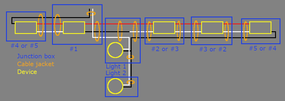
I believe the devices are interconnected as shown in the sketch below:

wiring sketch

I would do the following:

  1. Additional tests to confirm it's really wired exactly as shown in the sketch; make corrections as needed
  2. Print a copy of the corrected sketch and file it somewhere safe and obvious (inside the breaker panel door, maybe neatly folded and tucked into a junction box, etc)

Then, if you still want to install a dimmer only at #2 and delete all the other switches:

  1. Connect black to red at #4 and #5; cap the white.
  2. Connect red to red at #1; cap the loose black and white.
  3. Connect red to red and white to white at #3
  4. At Light #1: disconnect the black-white joint. Cap the black; combine the white with the other two whites.
  5. At #2: One of the reds is hot and the other is not. Figure out which one it is and connect the dimmer's line side to that one. The other red goes to the lights; connect to the dimmer's load side. One of the whites is neutral. Figure out which one it is and connect to the dimmer's neutral.
1
  • Awesome. I appreciate you taking the time to sketch this out too. I think I'm going to use this as a reference and see about chasing the wires to confirm your diagram. I'm obviously not an electrician, but understand the basic principles. Couldn't find a good example of how the wiring in mine might have been setup, so this really helps me understand what is going on. And thanks for the help on getting it wired how I was hoping to. I'm going to tackle this weekend.
    – Russ W.
    Commented Nov 9, 2021 at 20:27
0

Ceiling fans are not fans of dimming

While your setup isn't as scary (and constraining) as your initial diagram indicated, your proposal still has an issue: namely, that your ceiling fan will take a dim view of being put on a dimmer, leading to noises and eventual damage to both the dimmer and the fan. Instead, you need to provision a fan speed control for your fan, and that leaves you with only a few options:

  • First, you could wait this project until next year, when Inovelli will have their Z-Wave combo fan/light controller (the LZW36-SN) available again (it's out of stock at the moment). Since it uses a ceiling module, it'd require a fairly minimal amount of wiring, not far off from what it'd take to install your current dimmer.
  • Second, you could install a Z-Wave ceiling fan controller at the box, controlling the red wire up to the fan, while repurposing the black wire to the lights as an always-hot for a Z-wave micro-dimmer module in the fan/light box. This'd give you something implementable in the Z-wave ecosystem right now, at the cost of slightly harder wiring and much more complicated setup/commissioning.
  • Or lastly, you could go with a different system; my lean is towards Insteon, since it fares well in "spot" situations like this, and has a ceiling fan module (FanLinc) available for it that supports both fan and light control. You'd need a keypad at each wall station with always-hot and neutral run to it, but the fan module could then sit at the fan/light box and control both lights and the fan from there, preventing wiring from becoming a bottleneck.
2
  • I very much appreciate the feedback. I'm actually not intending on using the Inovelli Dimmer as a dimmer but intend to set it at 100% and disable the relay. I was then planning on using a flashed Sonoff iFan04 to control the fan/light combo and Hue bulbs in the other light fixture. The dimmer function of the Inovelli would then only work by intercepting the button presses in Home Assistant and issuing the appropriate commands to the Hue bulbs and iFan. I will probably go with the Z-Wave Inovelli fan/light controller when it becomes available, but wanted some independent control until then.
    – Russ W.
    Commented Nov 9, 2021 at 20:25
  • @RussW. -- Inovelli makes a switch (the LZW30-SR) that can be used instead of the dimmer (a dimmer on 100% isn't a straight pass-thru and can still damage a fan as a result) Commented Nov 10, 2021 at 2:42

Your Answer

By clicking “Post Your Answer”, you agree to our terms of service and acknowledge you have read our privacy policy.

Not the answer you're looking for? Browse other questions tagged or ask your own question.