1

My living room has a series of two outlets that I would like to convert to split receptacles, with the top half always live and the bottom half controlled by a pair of 3-way switches. Both switches will be new additions.

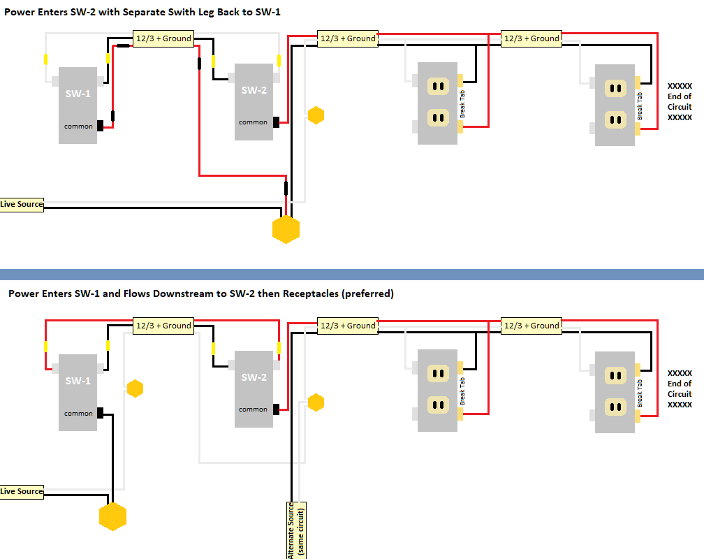
I would like to run this branch in the direction the power currently flows: Breaker > New Switch Location 1 (SW-1) > New Switch Location 2 (SW-2) > Outlet 1 > Outlet 2. This is what is depicted in the first image below.

Rough Layout & Flow

It would also be fairly easy to go: Breaker > New Switch Location 2 > Outlet 1 > Outlet 2 .... with a separate switch leg doubling back from SW-2 to SW-1. While this can work, it is not my preference.

Below are the two wiring mock ups I've put together. Note that there will a separate power source (from the same circuit) entering both of the new switch boxes (for unrelated reasons), which is why that appears in the second option.

Wiring Options

Thoughts? Are both correctly wired? If not, what did I get wrong? Am I missing another, simpler option?

Thank you in advance!

2 Answers 2

1

Entering at Switch 2 works...

The good news is that you can bring power in at switch 2 without issue. The three-way complex becomes an ordinary "spur" setup at this point, with a common wire and two travelers in the cable between Switch 1 and Switch 2, and thus doesn't impose any complications on the rest of the wiring, which looks the same as if you were wiring any other set of half-switched receptacles.

Note that since neutral is available at Switch 2, that covers the 404.2(C) requirement for neutrals to be present at switch locations, so you don't need to worry about bringing neutral over to Switch 1 in this case.

However, your plan for entering at switch 1 fails the Code test

Your problem with your preference for entering at switch 1, though, is that by splicing the neutral from the always-hot "alternate" feed and the neutral that traveled along with the traveler wires together, you've created a parallel, or "looped", neutral path. The resulting split in current flow creates a magnetic field between the two wires, which is bad because that field can heat ferrous metal pieces in your walls up like pans on an induction range. (It's also an EMI issue, but not one modern gear is susceptible to, due to CRTs being obsolete.)

As a result, the NEC prohibits such a configuration as an effect of how 300.3(B) and 310.10(H) are worded. In order to fix this, you have to bring always-hot to the second witch box alongside the travelers and neutral, which requires a 12/4 cable instead of the 12/3 you were planning on using (or 5 12AWG THHNs in a 1/2" ENT aka smurf tube, if you wish to roll that way instead). Once you have that straightened out, though, you should be good to go.

9
  • Can't thank you enough for this! I read it a half dozen times and understand the error in my thinking. I had a hunch 12/4 was probably required for Option 2. I may go that route, but I'll probably just go with Option 1. A followup Q: I'm now spooked about a split current magnetic field, which is a good thing. Assuming I go with Option 1 (ordinary spur; no loop), is it still a problem to have two separate power sources entering Switch Box 2, even if they are never joined? The feed "forks" in a junction box in my crawl space, with one spur going off to SW-1 and the other spur going out to SW-2.
    – kb406
    Commented Jan 1, 2021 at 20:16
  • 1
    @kb406 Stick to the "tree rule" in your cabling, and you auto-win: currents MUST be equal up any branch. No loops, no way for currents to imbalance. You can visit the same junction box with 2 branches, but there MUST be a "great wall of China" between the two groups of cables. I generally view this as "asking for trouble" and encourage 2 side-by-side boxes at that point. Smart switches are here to stay, and that means novices changing them everytime some new tech rolls out. Commented Jan 1, 2021 at 20:24
  • Yeah, having to "firewall" two sets of neutrals within a box is counterintuitive to folks who have been conditioned to residential wiring norms Commented Jan 1, 2021 at 20:57
  • @kb406 -- it isn't limited to "smart switches"; timers, advanced dimmers, and other such gizmos also will require neutral more and more these days Commented Jan 1, 2021 at 20:59
  • Ugh, I hate "smart" anything. So I doubt I'll ever add something like that. But you're right that future owners will inevitably do so. And I now see your follow up, that this includes advanced dimmers and all sorts of stuff.
    – kb406
    Commented Jan 1, 2021 at 21:01
1

Below are the two wiring mock ups I've put together. Note that there will a separate power source (from the same circuit) entering both of the new switch boxes (for unrelated reasons), which is why that appears in the second option.

You can't do that.

You cannot bring power into 2 places on this circuit.

When you consider how AC power cables (whole cables) are routed, this MUST be a "tree" topology (any combination of star and string/spur)... - but there cannot be loops.

As you've drawn your last diagram, you have a loop: Service panel via "Live Source" cable to switch 1 to switch 2 via "Alternate Source (Same Circuit)" cable back to service panel. NOPE.

The reason you can't do this is peculiar to AC power, and relates to induction and eddy current effects. Also maintainability by "the next guy" who would never, ever expect this. On a DC electronics circuit board, have a field day :)

As ThreePhaseEel states, Code does not require neutral over at Switch 1. If you want it for some reason, you'll need to either run /4 or /2/2 cable... or run conduit (e.g. "Smurf Tube") between them and fit any wires you please. Not allowed to buddy up two /2 cables to make a /4. Again the loop thing.

6
  • Thank you a ton for your response! I really appreciate it. I asked ThreePhaseEel a follow up below. Would love to get your thoughts as well. You said that I "cannot bring power into 2 places on this circuit." Does this mean splicing? Or do you mean two feeds in one switch box is forboden, even if they never splice together? The power feed for this circuit enters this part of the house between the two switch boxes. I installed a junction box and split the power into two runs. Is it alright to have both feeds ultimately enter Switch Box 2, so long as they aren't spliced together at any point?
    – kb406
    Commented Jan 1, 2021 at 20:23
  • 1
    @kb406 -- the big caveat is that not only can you not splice the hots back together, you can't splice the neutrals back together either, which means that you need separate neutral wires to carry the two feeds downstream Commented Jan 1, 2021 at 20:58
  • Gotcha. That makes perfect sense to me. Even if neither hot nor neutral are spliced, is it still an issue to have two different branches of the tree flowing through a box? I suppose even if there technically wasn't, just because I know what's going on doesn't mean the next person other than me going into that box will...?
    – kb406
    Commented Jan 1, 2021 at 21:07
  • @kb406 Is there any earthly reason you can't just put them in separate junction boxes? A 1-gang for SW1 with nothing but a /3 entering it... and right next to it, a ?-gang for whatever that other circuit will power? No wires passing between the 2 boxes. Is that compatible with your plan? Commented Jan 1, 2021 at 21:16
  • That is possible. This is a retrofit, so I'm using old work boxes. I'll have to see if putting a 1 gang next to a two gang box works size-wise for a 3-gang faceplate. That does seem like a wise solution, if workable.
    – kb406
    Commented Jan 1, 2021 at 21:31

Your Answer

By clicking “Post Your Answer”, you agree to our terms of service and acknowledge you have read our privacy policy.

Not the answer you're looking for? Browse other questions tagged or ask your own question.