This isn't terribly hard now that we know what it is we want here
The good news is that you look to have all the necessary wires in place, save for a grounding pigtail to the back of the box since this is a conduit job and your switch-receptacle lacks self-grounding clips. The bad news is it'll require a bit of pigtailing to wire this up, so you'll need a wirenut suitable for 3 12AWG wires and a couple of short (3-6") lengths of black 12AWG stranded THHN.
First off, we prepare the box by using the 10-32 screw on our grounding pigtail to attach it to the 10-32 tapped hole in the back of the box; if there is no such hole, then you can drive a Garvin GSST into the back of the box and use that to attach your grounding pigtail.
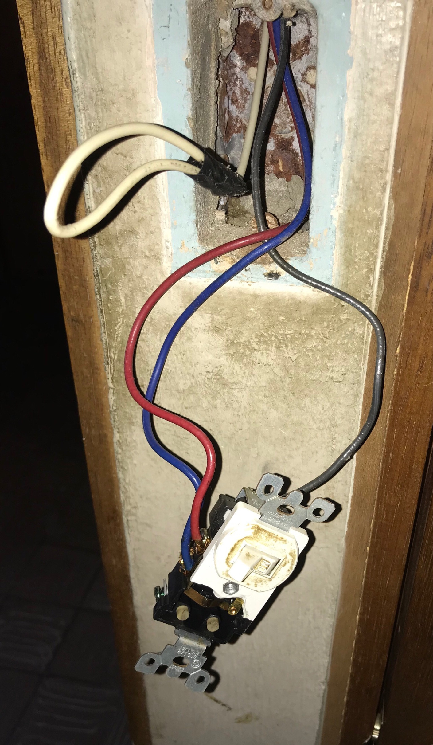
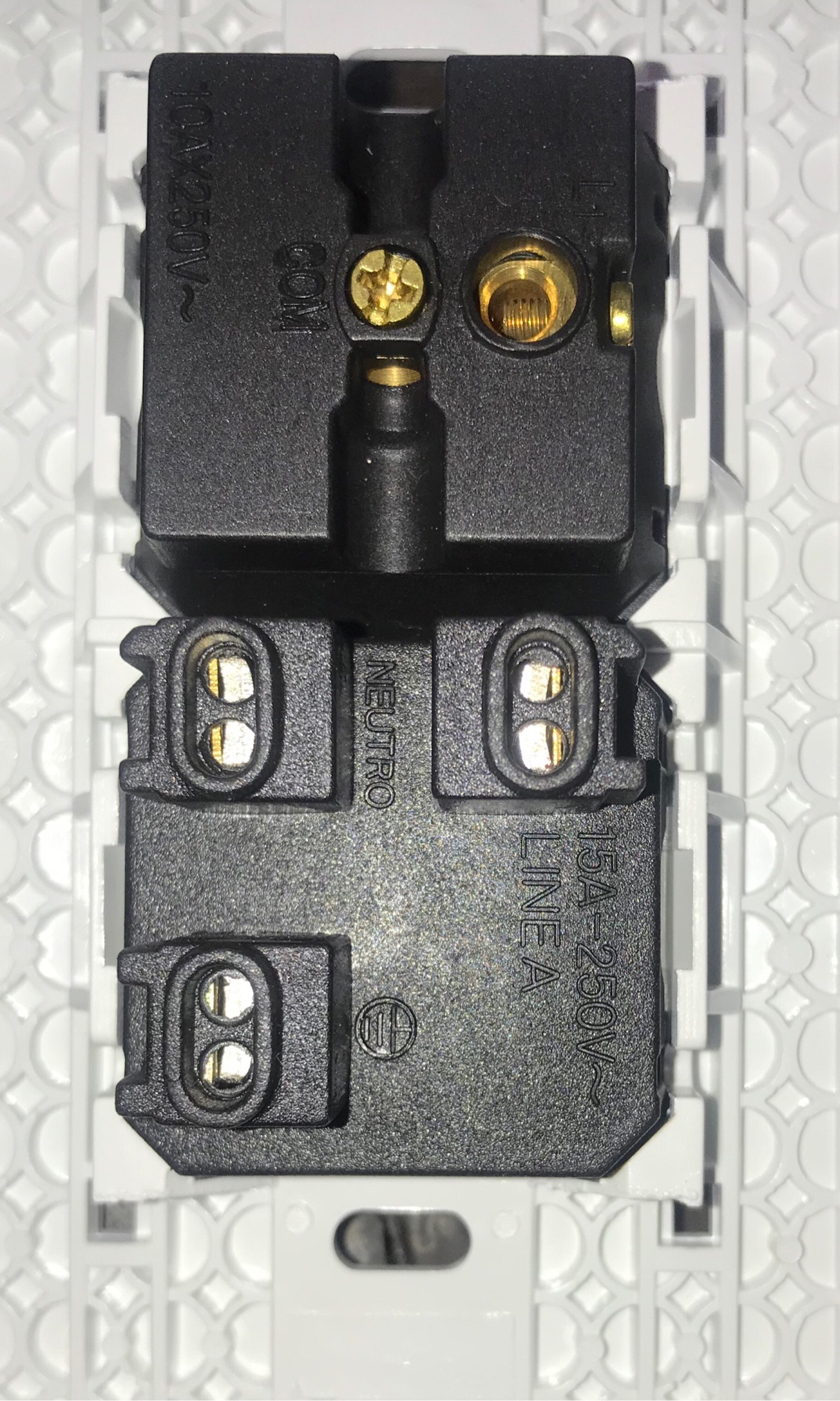
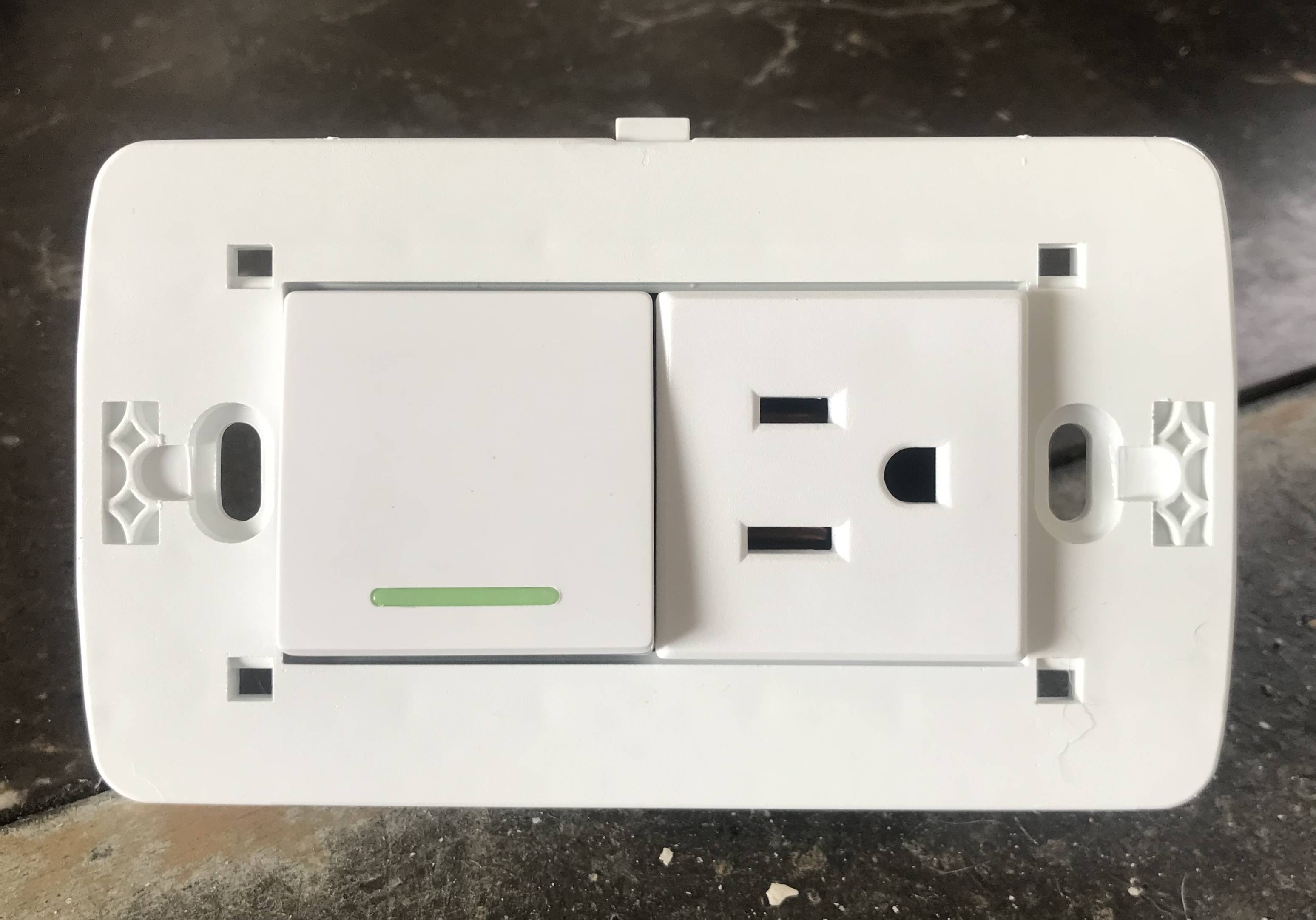
We then can move onto preparing the switch-receptacle; one of the black pigtails is attached to COM, while the other is attached to L1. Once that's done, we can start wiring up the receptacle. The grounding pigtail goes to one of the grounding terminals on the device, while the white wire gets untaped and connected to a neutral terminal on the receptacle part. One of the black pigtails from the switch section goes into one of the line terminals on the receptacle portion, while the black wire from the wall goes into the other line terminal on the receptacle end. Finally, the other black pigtail gets nutted with the red and blue wires from the wall.
Once all that's done, you can button up the box, turn the breaker back on, and enjoy your new switch-outlet!
 As you can see from the old wiring, the blue and red wires are connected to one side of the switch, the black wire is connected to the other side, and the white wire is not connected to anything.
