1

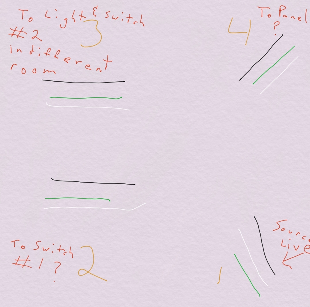
wire layout

I removed a light fixture, box and octagon to install an led recessed light that doesn't require a jbox. There were 12 wires crammed in there and when removing the box the tags I had to keep track came off (r.i.p. my DIY soul...)

I can't seem to figure out how to add the light fixture to this mix of wires and keep the switch for it working.

If I wire the black wires from nm1, nm3, nm4 and the neutrals from the same, the light in room 2 functions properly with its switch. How do I add the light fixture and nm2 into this and keep it's switch functional?

I assume nm4 is to the panel because of its older sheathing and also because wiring just nm1 and nm3 didn't complete the circuit. Nm1 and nm2 together didn't yield anything either.

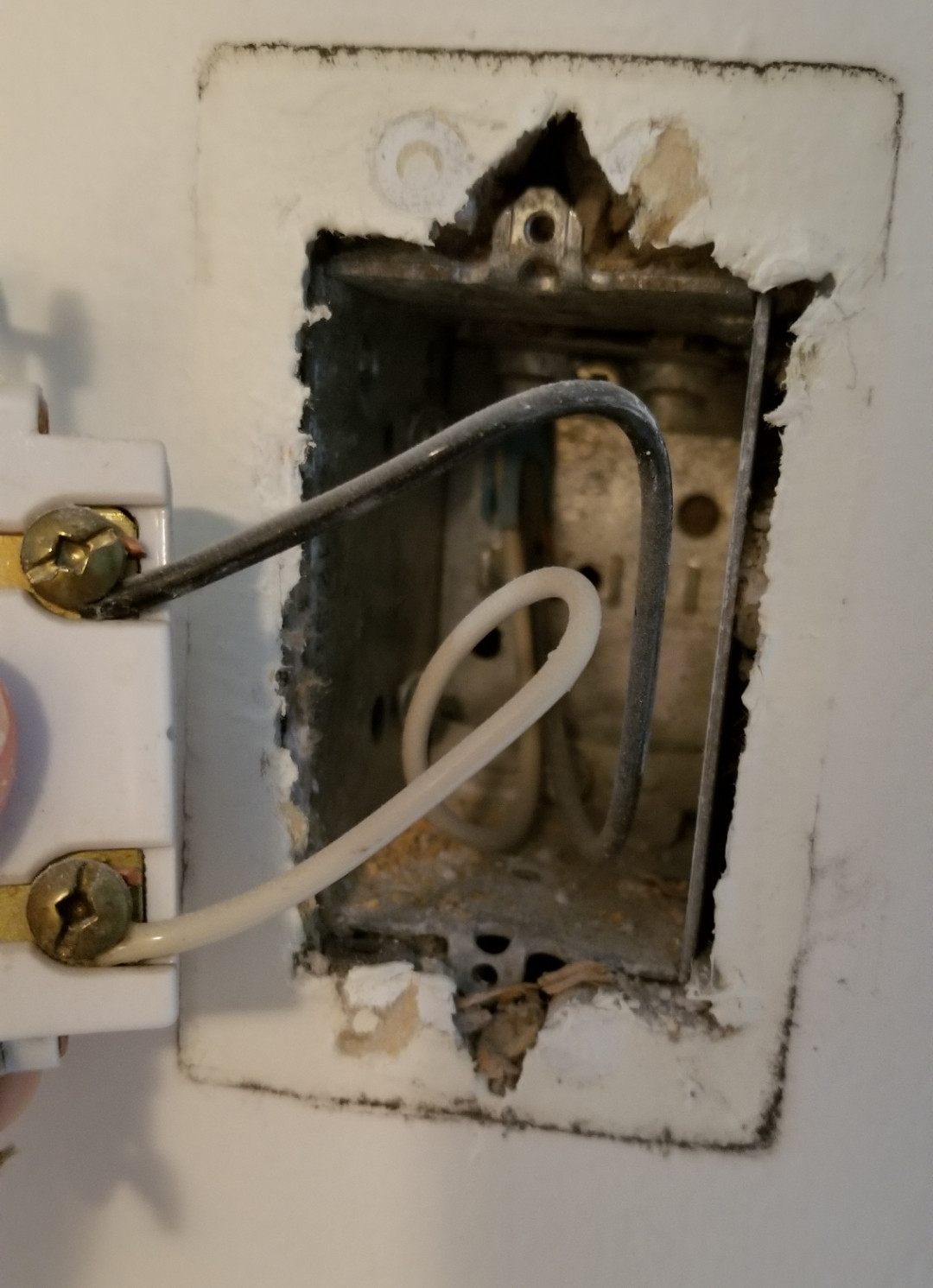
edit 1 picture of switch #1 box

7
  • "to panel ?" You need to know where this goes and verify the source.
    – JACK
    Commented Jul 11, 2020 at 12:54
  • Can you post a photo of the inside of the box for switch #1 please? Commented Jul 11, 2020 at 15:16
  • @JACK - i don't think I have the tools to trace nm4 to its source, but it is the only cable heading in the direction of the panel grouping.
    – Jon AB
    Commented Jul 11, 2020 at 16:21
  • Why do you think that NM1 is live? Commented Jul 11, 2020 at 17:41
  • @A.I.Breveleri when I turn the breaker on, the non contact voltage detector flags that wire as live, I can recheck though.
    – Jon AB
    Commented Jul 11, 2020 at 17:46

1 Answer 1

1

So you currently have the black wires from NM4, NM3, and NM1 connected together, and similarly the white wires from NM4, NM3, and NM1 connected together. What you probably have is power arriving via NM4 and being distributed to other rooms via NM3 and NM1.

You can verify this by temporarily disconnecting NM3 or NM1 and observing what parts of your house go dark. (You have already done this for NM3.)

It is also possible that NM4 and NM1 are on separate breakers. Investigate this possibility by temporarily separating the bundles of three black and three white wires, temporarily connecting a load (such as NM3) to each of NM4 and then NM1, and observing which breakers control NM4 and NM1.

NM2 seems to go to switch #1. You can verify this through contact testing, or you can just assume the cable doesn't make any other stops along the way. If this switch formerly controlled the light that you removed then this is a safe assumption.

Now -- to connect your new light and switch #1.

  • Connect the white wire of NM2 to the bundle of three black wires at the light. Color the white wire black (or any color other than white, gray, or green) with paint or a bit of tape.
  • At switch #1, color the white wire in the same way. This marks the white wire "reused as constant-hot" at both ends.
  • Back at the light, connect the black wire from NM2 to the black (hot) wire of the new lamp.
  • Connect the white (neutral) wire of the new lamp to the bundle of three white wires at the light.

Please be aware that this installation, while safe, is not up to current code, because there is no neutral connection available at switch #1. You are carrying a technical debt, i.e. the future installation of a smart switch at the location of switch #1 might require replacing NM2.

I believe it is proper to replace your ceiling lamp in this way because, in terms of code compliance, you are at least not making things worse.
1
  • you sir, are brilliant! 100% right on the panel wire being the actual source, I didn't use the non contact far enough away, and the sensitivity threw off what I thought was the source. Thank you 3000!
    – Jon AB
    Commented Jul 12, 2020 at 0:32

Your Answer

By clicking “Post Your Answer”, you agree to our terms of service and acknowledge you have read our privacy policy.

Not the answer you're looking for? Browse other questions tagged or ask your own question.