23

We are looking to install two NEMA 14-50 outlets for our kids to charge their electric cars, and I'm confused about wire choice. I thought I understood the correct wire to use, but then ran across a Tesla document that said something completely different than I was expecting.

Tesla has published installation instructions here that recommends 6 AWG for up to 150 feet. Here is a screenshot:

Tesla Instructions

However, when I search online for AWG charts, I find many results that all agree with each other, such as this one from here:

AWG Chart

Using these charts to spec out a 150 ft circuit, even allowing for a 10% voltage drop, I see that I need at least 1 gauge wire for 50 amps. If I want a 3% voltage drop (which I assume an electric car would need), then I should be using 4/0 at least. According to this chart, 6 gauge wire would only be sufficient out to 15 ft for 50 amps (or 50 ft if we allow for 10% voltage drop); neither of which is close to the 150 feet suggested by Tesla.

Given the clash between my internet-educated understanding, and Tesla's official publications probably written by electrical engineers, I have a feeling that the incorrect party might just be me. How is my understanding incorrect, and what gauge wire is actually needed for a 50 amp 14-50 outlet?

8
  • 10
    That chart looks way off. Consider: 12 awg used through a house - easily 50 feet or more - is standard everywhere for a 20A circuit. This chart would have you jump to 4 awg when typically even 10 awg would be considered overkill. Commented Jun 18, 2020 at 14:52
  • 3
    That chart doesn't agree with other calculators, I get less less than 3% drop #6 copper, 150 ft., 50A. Here are two calculators southwire.com/calculator-vdrop calculator.net/… Commented Jun 18, 2020 at 14:54
  • @nosparksplease I like the south wires voltage drop calculator also. was coming back to add that but, since you already have it +, the only thing this new one has not totally obvious is the parallel sets. you put a 1 in there if a single run like most here are using.
    – Ed Beal
    Commented Jun 18, 2020 at 21:48
  • 7
    I would point out that this chart is from a site for boating and marine electrical wiring, not household wiring. It's possible that could be why the overkill gauges.
    – barbecue
    Commented Jun 19, 2020 at 13:31
  • 1
    One thing to consider is that the load is most definitely not 50 Amps. 50 Amps is just your breaker size, if the load were 50 amps for a long period of time you would likely experience breaker trips. The standard design practice is for the maximum sustained load to be at most 80% of the breaker size - so 40 Amps.
    – Glen Yates
    Commented Jun 19, 2020 at 15:13

7 Answers 7

62

That chart is from BlueSea - they make marine DC power system components (mostly 12V and 24V). Voltage drop effects are completely different at 12V vs. the 240V used by this EV charger. Disregard that chart.

Plugging the actual scenario (240V, 6AWG, 40A load, 150 feet) into a voltage drop calculation indicates that the worst possible voltage drop will be only 1.98%.

7
  • That appears to have been my problem. I typed "AWG chart amps" into Google, and the 3 results that I picked out and compared against each other were apparently all for 12V systems. Thank you for the calculator link; I will use it to size our run. If I decide to run one wire to feed two 50-amp outlets, can I just use the calculator but put in 100 amps load, or is there anything extra required to run two outlets off one wire?
    – Nicholas
    Commented Jun 18, 2020 at 16:22
  • That would be better posed as a separate question, but I'm fairly certain you cannot hang two 50A receptacles off a 100A breaker an corresponding wire. You would most likely need a local sub panel.
    – nobody
    Commented Jun 18, 2020 at 16:55
  • 19
    +1 To expand on the comment "Voltage drop effects are completely different at 12 V vs 240 V): Apart from A/C vs D/C, the voltage drop is effectively the same across the wire (e.g. running 40A through wire with 0.1 ohm of resistance gives a 4 V drop; because V = IR). However, the key is that the effect of the voltage drop is different: a 4V drop with a 240 V supply is a 1.7% drop from the supply voltage while a 4V drop with a 12V supply is a relatively massive 33% drop. Commented Jun 18, 2020 at 19:27
  • 1
    @statueuphemism: The effects are even worse than that when driving resistive loads. If wire resistance would take a 12-volt supply down to 8 volts, that would reduce the power reaching the load by more than half (it would reduce the power from the supply by a third; the load would receive 2/3 of that reduced about).
    – supercat
    Commented Jun 19, 2020 at 3:59
  • 1
    @Nicholas smart chargers exist that can communicate with their neighbours and let 1 car charge at a higher current and 2 cars at a lower current. That way you can put 2 50A chargers on the same breaker without chancing that they trip the breaker. Though those will be for commercial parking lots. Commented Jun 19, 2020 at 10:22
15

Oh, that math is wrong!

The chart is fatally flawed: it fails to state supply voltage. (It's probably 12/24V).

For 240V circuits, I don't even bother to crunch the numbers until the run is 180' or more.

But even if we're operating under the rules of the oppressive Canadian regime, #6 is good for 204 feet, eh?

In fact, you can use #8 wire for 50A under certain conditions (NOT NM/Romex nor UF-B). At 150' your 39A-actual charger will get 3.45% voltage drop, which is perfectly acceptable... and that's #8.

Just the same, look at the UL-approved instructions. If they require #6, then that is the last word on the subject.

What you should really do, though

Your idea of going bigger is on the right track, though. Here's why: Tesla keeps making the chargers bigger. Can you say with a straight face that you'll never want the bigger "100A" charger? Well, then, might want to run that #1 after all. Aluminum of course.

#1 aluminum will support that future 100A charger just fine. Nobody uses copper for runs this large and long. Even #6 Cu is large enough that you should seriously consider aluminum instead. If you only wanted 50A, then #4 aluminum would do, unless it was in certain wiring methods which would permit 75C running, then #6 aluminum would do.

I would lay 1-1/4" conduit, as a continuous pipe from panel to EVSE socket. (with access points as needed for pulling, typically at corners). That allows the higher temp (smaller) wire. For 50A, pulling #8 copper wire will be trivial in such a large pipe. At some future point, you'd have no trouble pulling 2x #1 aluminum, since the pipe is oversized. It could even support as large as 3/0 wire, to support next year's EVSE :)

And no offense, but for green novices, I like the idea of having you route empty conduit. It's vastly easier, safer and more novice friendly than trying to wrestle a 150 foot long alligator. You get to work in small segments, and you get to iterate at your leisure - post pix and get feedback - until it is perfect. Then you're at a checkpoint, where you can either decide to self-pull wire or just bring in an electrician for the coup de grâce.

It's also compatible with Harper's Law: Buy the wire last. i.e. at the last possible moment.

I am surprised Tesla wants a 14-50 recep, because that requires pulling a neutral wire that any sensible EVSE should not need at all. I suspect they go for that because it's widely used by RV's.

6
  • Nobody is going to charge 100A at 240, so far as I can tell from news in BEV forums. HIgher power-level chargers (for home use) at some point will require either parallel feeds or access to 440VAC. Commented Jun 18, 2020 at 18:01
  • 1
    Tesla already sells the High Power Wall Connector, 100A breaker 80A practical @CarlWitthoft I don't think they sell Superchargers for homes, but if OP can get a 480 drop, that 1.25" conduit will support 3x1/0Cu, for 125kw @ 480delta... almost a V2 supercharger. You're right, better use 1.5" conduit ... Commented Jun 18, 2020 at 18:19
  • 6
    @Harper The math is right, just for a different supply voltage. Commented Jun 18, 2020 at 18:53
  • 4
    I really don’t like seeing the larger chargers in residential, it imbalances the system for the short amount of time they are on , most folks don’t realize when the grid is imbalanced more coal or natural gas is burned than normal, hydro levels can change but not as easily as coal or natural gas generation so that’s where the “surge loads” are powered from specially at night.
    – Ed Beal
    Commented Jun 18, 2020 at 21:42
  • 1
    @EdBeal I have absolute faith in the free market to correct that problem. For instance, an arcane, turn-of-the-century rectifier called a rotary converter (not to be confused with "rotary phase converter") has the side-effect of correcting power factor for the entire distribution branch it is on. The "battery" as it were is the physical rotating mass of the machine. Now if you weren't pulling DC off of it, a bunch of brushes go away, and that's the maintenance headache. Run it in a vacuum chamber to cut wind losses, it could be quite efficient. Commented Jun 19, 2020 at 17:18
4

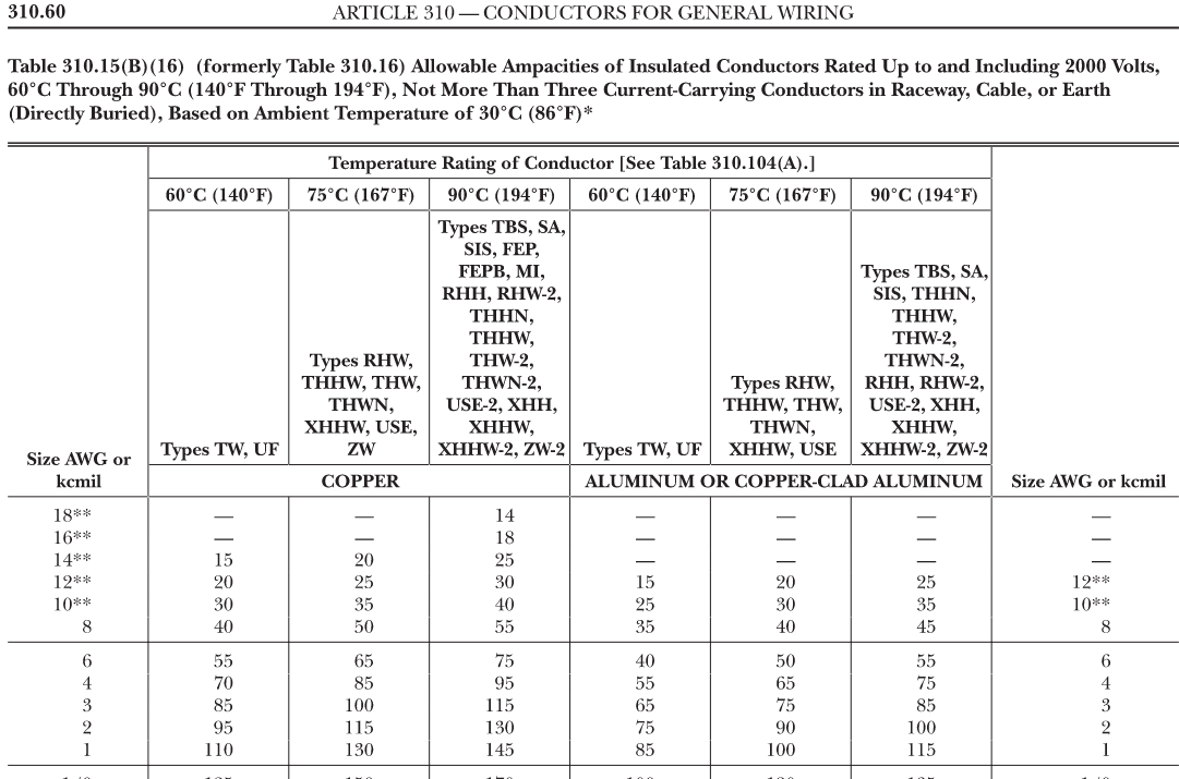
The ampacity chart you are looking for is NEC Table 310.15(B)(16).

enter image description here

Tesla's instructions to use #6 copper allows the use of any insulation type, but these days most insulation is high temperature and you can use the 75-degree C column which would allow you to go as small as a #8 copper. I should emphasize that most wire is now rated at 90 degrees C, but you can't use that column to choose wire size because almost no terminals are rated above 75 degrees. The temperature rating of a system cannot be more than the lowest rated component.

You could also wire this with aluminum, but in that case, you would need a minimum of #6 (75 degree) or a #4 (60 degree). If you use aluminum, however, you must also use anti-oxidation compound on the terminations because aluminum naturally reacts with air and forms a tough, highly resistive oxide coating that causes overheating at the terminations.

I would probably put this in with #6 copper for the 2 line conductors and the the neutral along with a #10 equipment grounding conductor (sized per NEC Table 250.122). This would all fit in a 3/4" conduit, but I would be inclined to use 1", especially if you are using PVC. By the way, an easy tool for calculating conduit size can be found at: http://www.electrician2.com/calculators/racewayfill_calc_rev0326.htm.

I hope this helps.

2

Most runs under 100’ don’t need to be upsized. 3% is a guideline not a code rule for the NEC.

For listed equipment the MFG instructions over rule the NEC.

2

First thing: which adapter cable do you have - and from which Tesla model? I have an older (2016) M-S, and the cable is designed to run 40 A continuous from the NEMA 14-50. However, the newer adapter cables, such as provided with the Model-3, are a downgrade & the internal electronics won't allow more than I think 30 or 35 A continuous.

In any case, NEMA 14-50 means it's rated for 50 A / 240 peak but only 40 A continuous.

Next thing: all Tesla adapters (and the internal charging controllers) will monitor the line for voltage drop, so as to ensure the car doesn't try to pull so much current that the feed line overheats. I recommend you hop on over to Tesla forums, either at tesla.com or teslarati.com (among others), where you can get a lot more information specific to Tesla charging, as opposed to generic 240VAC/40A systems.

2

Wrong chart. That is marine wire rating for 12/24v DC.

You need NEC wire ratings for 240v AC. When you obtain that via Google, you will see that 6 AWG THHN is rated for 75A as long as the bundling, ambient temp, and run length limitations are not exceeded. 10 AWG is sufficient for the ground wire. Your 14-50 outlet is rated for 50A, so that will be your maximum circuit breaker size.

Consider installing NEMA 6-50 instead of 14-50. You will need to buy the corresponding adapter for your Tesla mobile charger. You cannot charge an RV on 6-50, but you run one less conductor and don't need GFCI.

Get an industrial grade outlet.

1
  • 1
    You still need GFCI on a 6-50, even under the 2017 NEC (the section that requires it got accidentally omitted from the Codebook, there's a TIA that rectifies that) Commented Jun 19, 2020 at 23:06
0

The Tesla spec sheet for installing a NEMA14/50 receptacle is for the GEN1 cords, the new or not so new GEN2 cords which have been around for 5-6 years now limits the draw to only 32A and Tesla's new spec sheet states #8 wire with a #10 ground wire. unless of course the run is over 160', then you might need to increase the wire size to compensate for the voltage drop, an depending on the distance will determine which size wire you would need to install.

1
  • 1
    Suggestion - you could improve your answer by citing a reference to this information. Commented Feb 14, 2023 at 23:28

Your Answer

By clicking “Post Your Answer”, you agree to our terms of service and acknowledge you have read our privacy policy.

Not the answer you're looking for? Browse other questions tagged or ask your own question.