2

I bought a new fan with an LED light, so the dimmer switch connected to the old fan has to be switched. When I pulled out the switch, I found a confusing set up.

Wiring instructions

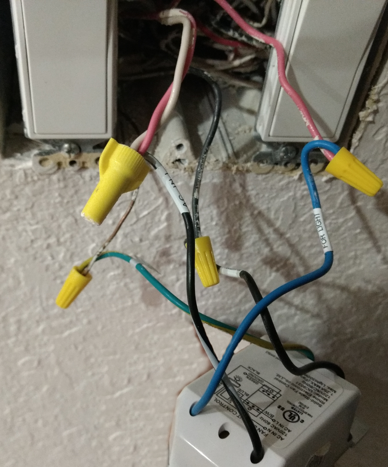
The current wiring colors don't quite match. Currently it is hooked up as:

  • Switch's B/W wire is joined to a Red and White coming from the box
  • Switch's Blue wire is joined to another Red coming from the box
  • Switch's Black wire is joined to a Black wire coming from the box
  • Ground is as expected.

Here is an photo of the current switch:

enter image description here

The 4-connection switch in the other room is wired as expected, however, the white wires don't have the expected black tape on the ends.

My question is: what is the appropriate way to replace this custom dimmer/fan switch with a standard 3-connection switch - which wires go where and what to do with the extra red wire?

7
  • 1
    You are using words in ways that are creating unclarity. "Cables" have multiple insulated "Wires" inside a sheath. Where switches are concerned, "Poles" has a specific meaning that applies to industrial switches, and has nothing to do with the number of wires going to the switch. "4-way" also means a thing that I don't think applies here. Can you find other words (preferably not jargon) that describe what you mean? You can edit the question to improve. Apr 1, 2019 at 0:09
  • Photos would be even better
    – Jeff Cates
    Apr 1, 2019 at 0:31
  • Can you post some photos of the wiring configuration, please? Apr 1, 2019 at 0:51
  • @Harper I've edited the post to use the term wires which is what I meant, sorry for the confusion. By "poles" I'm referring to the connection points on the switch, which are either screw-downs or push-ins, the 4-way paddle switch has 4 screw-downs plus a ground screw. The 3-way paddle switch has 3 screw-downs plus a ground screw. Any help you can provide would be appreciated.
    – krotos
    Apr 1, 2019 at 14:46
  • @JeffCates I've added a photo of the current switch that I'm trying to replace.
    – krotos
    Apr 1, 2019 at 14:47

1 Answer 1

1

This is pretty easy, because whatever's happening with the red and white wires there is none of our business.

It's like if you call in a realtor and prime contractor, and they show up at the same time and look alike... that's none of your business.

(You can take it apart if you want to... but then you become responsible for everything going on in that area of the circuit, and I gather you don't have the skills to pay those bills. Such unnecessary dismantling almost always ends in an electrician call. I do have the skills, and those colors unnerve me, and I'd do some investigating, but I wouldn't touch it until I'd fully mapped it out.)

So, all ground wires everywhere except the old Soviet Bloc are bare, green, or yellow/green. All grounds go together. Done.

The black/white wire is supply hot, and it's not unusual for supply hots to splice with other things to go onward to other points of use. So you leave that alone and just join the red, white and a pigtail to the "common" on your new duplex switch.

Except for grounds, color codes mean next to nothing because of the way cables are made. It'd be peachy keen if we could just buy red/black, blue/white, red/yellow/yellow or whatever combo you needed, but nope - cables are only made one way. So colors are pretty useless unless you swerve out of your way to use colored tape to mark wires.

The remaining two wires:

  • Solo-red from the wall goes to the light.
  • Solo-black from the wall goes to the fan.

Each of these goes to a switched-hot screw on your duplex switch.

1
  • Does this photo match what you're recommending? imgur.com/lQvrQZL Thanks for your assistance!
    – krotos
    Apr 2, 2019 at 0:47

Your Answer

By clicking “Post Your Answer”, you agree to our terms of service and acknowledge that you have read and understand our privacy policy and code of conduct.

Not the answer you're looking for? Browse other questions tagged or ask your own question.